Quantcast
Channel: MD's Technical Sharing
Viewing all 63 articles
Browse latest View live

Unlocking the Linksys SPA2102 Phone Adapter

$
0
0
I got myself a free Linksys SPA2102 SIP-to-PSTN adapter from a friend. However, to my disappointment, it is locked to iTalkBB and cannot be used with other providers. I searched for various methods and shared some of my finding here.

First, the SPA2102 supports both lines, namely Line 1 and Line 2. Some operators only lock Line 1, leaving Line 2 configuration free to change. If that is the case for your device and you only need to use a single line, simply use Line 2.

If that is not the case, enter the configuration menu (****) and try a user reset (877778#). Only do a factory reset (73738#) at a last resort! A user resets will only clear the SIP account settings whereas a factory reset will clear everything, including the web portal access passwords and set them back to manufacturer defaults. For an unlocked device, this will usually be either empty or easy-to-remember password (e.g. 0000). However, for a locked unit, this is a random number set by the SIP provider that locks the device on a per-unit basis. If you factory reset and gets your device to this state, you may as well buy a new one.

Next, try to enable the web portal access by 723646# and enter password 78778839#. After that, connect the WAN port to router and access Http://[ip address]:1980. Login with the following username/password  pairs: user/1234 or admin/58724687.

If the password is rejected, you'll need to find our what the password is. Luckily, the locked device will keep on posting to the settings provisioning server looking for updated SIP server settings, using the username/password in clear text. You need to use a network capture tool such as WireShack, and look for the following data packet from the ATA:

<Admin_Passwd ua="na">58724687</Admin_Passwd>

When you have successfully opened the Admin portal, remove all items from the Restricted Access Domains list. You should be able to configure both lines.

If none of the above helps, try to do a firmware update. There are 2 ways, one is by following this guide which basically asks you to open a URL on the device web portal, pass in the firmware URL and wait for flashing to be done. Another way is to flash via a Windows tool, see this.

Fixing "The CPU has been disabled by the guest operating system" when running OS X Lion on VMWare

$
0
0
My OS X Lion VMware image, which has always been working fine on my computer, a 2.53GHz Intel Core i5 HP notebook, stopped working when I migrated to a Dell Core i7 notebook. The machine would immediately stop at boot-up with the following VMware error message:

"The CPU has been disabled by the guest operating system. Power off or reset the virtual machine."

My first thought was that the VMware patcher to enable OS X guest on Windows was somehow not executed successfully. I tried to reinstall VMware, rerun the patcher, and install different versions of VMware many times but to no avail. I finally tried to enable verbose boot using:

sudo nvram boot-args="-v"

and the screen showed a little bit of more information, although not much useful:


There is no problem indicated by the above messages - it is simply part of the OS X boot process. The CPU was apparently halted as soon as the boot device was detected (indicated by the info 'root device uuid is...') without even attempting to boot further. Following a strange idea, I reverted the virtual machine to one of the previous snapshot, saved when OS X Lion was already running, and received the following warning about processor features difference:

The features supported by the processor(s) in this machine are different from the features supported by the processor(s) in the machine on which the snapshot was saved.

I chose to proceed, and guess what, my OS X booted up and functioned properly without further problems. For more than 2 weeks, due to time constraints, I simply worked with the virtual machine in that saved state, suspended it when done and reverting back to the snapshot (after saving all data) when I needed to reboot!

Recently I had some free time and determined to solve the problem completely. Following a Google search of the root device uuid message, I found this blog which describes a similar problem and the solution for VMware ESXi by editing the CPU ID:

- edit the VM settings with the VM powered off
- click on the Options tab
- click on the CPUID Mask menu item
- click Advanced
- scroll to the bottom of the window on the Virtual Machine Default tab
- under “Level 1″ set “eax” to 0000:0000:0000:0001:0000:0110:1010:0101.

I am using VMware workstation, which does not have such an option to mask the CPU ID. However, using instructions from this forum, I was able to change the CPU ID by modifying the VMX file and add the following line:

cpuid.1.eax = "0000:0000:0000:0001:0000:0110:1010:0101"

With this change, my OS X Lion booted up properly and there is no need to work with it in a saved state anymore.

But what makes OS X Lion dislike my new laptop's processor and refuse to boot up? The fact that the unmodified virtual machine can still work on the new processor with the previously saved state implies that the processor difference is probably not critical - it was most likely a check that disables the processor if an unwelcome processor is found! With further research I realized that my new laptop processor architecture is Ivy Bridge, as compared with Sandy Bridge in my old laptop. Max OS X Lion doesn't like Ivy Bridge architecture, and thus refuses to boot up unless the CPU ID is masked to make OS X think it's running on a Sandy Bridge processor. What a hassle created by Apple, the virtual machine would have booted up properly and saved me precious time troubleshooting without this check.

Luckily, according to my research, this is probably not needed with Mountain Lion, since it supports Ivy bridge natively. I have not had the time to verify this, however.

On a side note, when trying to connect your USB device to the Mac virtual machine via VMware menu, you may receive the following error message:

"The connection for the USB device was unsuccessful. The device is currently in use"

When this happens, first check if the error message is telling you the truth. Stop all Windows applications that are currently using the device, reboot your laptop and the virtual machine and try again. If that doesn't help and you're using a new laptop with USB 3.0 ports, most likely you've hit a known problem - VMware does not support most USB 3.0 chips on Windows host. The Linux version does, however. This means, on Windows, you must revert back to a USB 2.0 or USB 1.1 port to avoid this error. So much for backwards compatibility!

In my case, I was lucky. My laptop has 4 USB ports, 3xUSB 3.0 ports and 1xUSB 2.0 port. I plugged the device to the USB 2.0 port and VMware was able to connect the device successfully.

Testing V9999 dual SIM card & dual camera quad-band phone from eBay

$
0
0
I got myself a cheap quad-band phone with dual SIM card, dual camera, USB port, and QWERTY keyboard, among other things, for a cheap price from eBay:


This phone apparently has many features, according to the seller:

Band         GSM 850/900/1800/1900MHz
Display Size 2.2 Inch
Resolution   320 x 240 pixels
Screen Color 260K Colors
Audio        MP3/WAV/AMR/AWB
Video        3GP/MPEG4
Image        JPEG/BMP/GIF/PNG/GIF
E-book       TXT/CHM/DOC/HTML
FM Radio     Yes, can play radio without earphone
Card         SD card up to 8GB
Data         WAP/GPRS
Camera       0.3MP
TV           Yes, analog TV with antenna
JAVA         Yes
Bluetooth    2.0

I spent a day playing with the phone, just for the sake of curiosity, and share some of my findings below.

Overall
  • 2G (GPRS) only, does not support 3G mode
  • Proprietary charger and headphones, small keys and slow keyboard
  • The SIM card insertion direction printed on the back of the phone is reversed! This made me waste half an hour figuring out why the phone couldn't detected my SIM card
Voice/SMS
  • Outgoing calls/SMS are prohibited (incoming calls are still fine) until the SIM card is enabled by setting Settings > Dual SIM Switch > Use Default Mode and Settings > Dual SIM Settings > Dual SIM Open
  • It is a pain on this phone to send an SMS. The keys are tiny, too many menu options and too many pressed to switch between alphabet, symbols and numeric mode
  • Making and receiving voice calls seems fine during my testing
User Interface
  • New time zone prompt keeps on popping up. To turn off, go to Settings > Phone Settings > Auto update of date/time and set to Off
  • To enable key lock, go to Settings > Security Settings > Auto keypad lock. To unlock, press the BACK key (RSK) and #
  • Keypad tone default is ON. To turn off, go to User profiles > general > customize > Tone Settings > Keypad > Off
Data Connection
  • To configure GPRS, go to Services > Data Account > Add your GPRS APN here and Services > Internet Services > Settings > Profiles. Delete one or more existing accounts and add your GPRS profile pointing to the above data account
  • "GPRS/CSD connection exists" error will be shown if attempting to use camera when there is an Internet connection.
  • Many attractive options such as Entertainment News, Amazing Beauties, HD Movie, Ring Settings are unusable and report "No Services"
TV/Radio
  • TV works ok, although reception is a bit weak, but able to view most channels. Works without headset.
  • FM reception is a bit weak but otherwise work. Works without headset as well.
  • Consumes a lot of battery and lasts less than 1 hour with TV on.
Multimedia
  • Camera maximum resolution is VGA (640x480). Default resolution is QVGA. "Front camera" is actually on top!
  • Default Audio Player/Video Player reports "No Service", however File Manager can play some videos and music files (MP3, WAV)
  • Many video files can be played. Tested with 3GP and MP4 files. To play in full-screen mode press the A key.
  • DOC/CHM/HTML files are not supported as claimed. Only text files (TXT) are supported.
Browser
  • Default browser is very limited. Common pages, including built in facebook app default to Chinese versions with no font!
  • Opera Mini 3.3 is a good placement for the built-in browser
  • Opera Mini 6.5 crashes after showing splash screen, presumably due to low memory. Opera Mini 4.4 installs and works ok but is a bit slow. Only Opera Mini 3.3 Advanced Edition works well on this phone.
J2ME Apps
  • J2ME works in general. Installation can be from JAR files to either phone memory or storage card. Unicode is supported. Games are playable, albeit with tiny keyboard. Comes with some default games. Java apps and settings can be found in Fun & Games. Apps that consume lot of memory will hang at loading. Java apps launch in exclusive single task mode. Pressing the RED (hangup) key will terminate the app and go to home screen
  • Some apps such ABCMsn terminate upon connecting to network due to device prompts about airtime usage and the app cannot wait.
  • Some apps such as eBuddy can't work, the app will run and say "your phone does not have enough memory"
Bluetooth
  • Supports sending and receiving file via Bluetooth. Allows browsing remote Bluetooth folder as well.
  • Supports Bluetooth Audio service. To use it, user must start the connection from the device via Bluetooth >Search Audio Devices, otherwise connecting from Windows will say "Connection Failed". If successful, "Bluetooth Audio" will appear in Windows as a playback device. However, playing music on device still plays on loudspeaker, and attempting to play through "Bluetooth Audio" will cause the headset to be disconnected.
  • Support Bluetooth Serial Ports and act as GSM modem. Tested with Hyperterminal. Flow control must set to NONE for it to work. The modem is able to send SMS but cannot call out. "NO CARRIER" is reported if attempted, potentially because Bluetooth and phone share the same radio and can't be simultaneously on
 USB Connection
  • When connected via USB, the phone supports many mode, including USB charging.
  • Support USB mass storage mode for both internal devices & storage card
  • Support USB Webcam mode and works well with Webcam Viewer, up to VGA quality
  • COM port mode is included in the list of modes, however Windows 7 64-bit never finds drivers for it and I am not sure what this is for.
  • Java Connection is also included, however Windows 7 plays the "device connect fails" sound and I am also not sure what this is for. Perhaps to debug Java apps?
After finishing testing the phone, I put it in my drawer and did not use it again until a few months later when my main phone failed. This is when problem began to appear. The battery capacity is poor and lasts for less than a day even with little usage. Occasionally the phone would just hang and require a reboot. I complain to the seller and although he was nice enough to send me a new battery, my usage of the phone stopped a few weeks later when it failed to boot up and hangs at the charging indicator.


In short, just as many other cheap Chinese phones from eBay, this is good as a toy and for experimenting, but never as a primary phone. For that purpose, my old Nokia 3210 is far better and can still serve me well after all these years.


Marshmallow 7G Android 4.0 Wifi+3G Tablet

$
0
0
I recently purchased the Marshmallow 7G, an Android 4.0 tablet that has Wifi and 3G, supports USB hosts with HDMI output, and other features.The Marshmallow 7G is distributed through w3gear, a Singapore company, and is available for purchase online via w3gear's official website at a price of 289 SGD at the time of writing this article (Sept 2012).

The tablet has a home button, side volume buttons and a front camera:
On first look, this Android tablet is cheaper than the Dreambook W7, which I have mentioned in details in a previous article, and is also much lighter (345g compared with 500g or more for the Dreambook) and thinner. I decided to perform a thorough test of the tablet and share my finding here, which I hope will help others who intend to buy the tablet.

Overall

The default screen orientation is landscape and an accelerometer will rotate the screen to portrait appropriately. However, should you decide to turn off auto-rotation, the screen will default back to Landscape and there is no options to set to Portrait mode.

Same as the Dreambook W7, there is no restart option on this device. You can only turn the device off and turn it back on.

Call & SMS

As a 3G Android tablet, the device has the Android default Dialer and Messaging applications. Although making or receiving calls as well as sending/receiving SMS works fine, the default dialer has problems dialing USSD code. For example, if you are on a prepaid card and dial your network provider's USSD code of *100# to check account balance, the dialer would hang forever at the "Dialing" screen. No 3rd party dialer I tried would help, since the problem seems to  be in the radio firmware

The loudspeaker volume is also too soft even at maximum output. There is no headset option and calls are made on loudspeaker.

Internet Access

The device supports 3G, which works fine with my SIM card. However, it takes up to 5 minutes upon a cold boot for the device to lock on to a network provider. Once registered onto a network, 3G reception seems stable.

The default browser user agent defaults to a PC browser, which will just make loading web page slower. To overcome this, I use Opera Mobile.

Tethering works well in all my tests. Wifi reception is reasonable and the device connects to my home router with no issues.

Location Services

There is neither GPS support nor a compass on this device. Approximate location via Wifi/CellID is also not available, even though the device supports 3G and should, in theory, know its approximate location via the cell network. The Nook Tablet, however, can identify its approximate location as long as it is connected to a Wifi network.

Bluetooth & Peripherals

In my test, I am able to send a text file from a phone to the PC via Bluetooth. However, the device is unable to receive a file via Bluetooth - the PC reports timeout despite numerous attempts to tweak the Bluetooth settings. Playing audio via Bluetooth works fine, however.

USB host, one of the feature that convinced me to buy this tablet, works well. Mouse, keyboard and FAT16/FAT32 thumbdrives are supported, either independently or via a USB hub. The device comes with a proper adapter which would allow you to connect your USB devices to the micro-USB port.

I did not test the HDMI output. To stand any chance of having the Android screen projected on your LCD TV, however, you would need to have an appropriate HDMI (Female) to mini-HDMI (Male) converter.

Battery

Most of my tests with the device have been positive so far and I was intending to use the tablet for daily needs when I realized that the battery level was decreasing very fast. With 3G on, in standby mode with no major application running, the tablet battery is dead within a day or so. Try to play a video with both the phone radio and Wifi off, using your headset, 15% screen brightness, full battery and the battery is dead within 2.5 hrs. Although I can understand the battery drain while playing video, I do not understand why the device consumes so much battery even in standby mode with no other applications.

All this indicates poor battery capacity, which I can tell from the weight of the phone. It should have been heavier to support a higher capacity battery.

The verdict

Giventhat I explored the Dreambook W7 a year ago and was pretty disappointed, I was pretty surprised when testing the Marshmallow 7G tablet for the first time - almost everything worked as described. However, the excitement did not last long when I realized that the poor battery is a show-stopper for this device - the short battery life would not allow you to use it for anything other than experimenting. On that basis, I resold the device and purchased a Nook Tablet, which although does not feature 3G, can still serve me well due to its excellent battery life - a month on standby and up to 8 hrs of continuous usage.

Using SOAP web service in an iOS application

$
0
0
I recently needed to connect to SOAP web services written in .NET/PHP from one of my iOS applications when I realized that is there is no built in support for SOAP messages (although iOS5 and above has support for JSON via the NSJSONSerialization class). Obviously I could decide to construct the SOAP XML messages manually and POST them to the web service via NSURLRequest, I soon realized that this approach is not feasible due to the many (50+) web services that my application needs to use.

Fortunately I find wsdl2objc, an Objective-C code-generator for SOAP web services which automatically parses the web service WSDL definition and generates the appropriate classes to send a request and parse the response. 

The tool is a simple Mac OS app that asks you for the location to your web service WSDL definition, which can be a URL or a local file, and where to put the generated code:


Supply the required information and press Parse WSDL. The tool should quickly finish and give you the resulting source code files, which look similar to below:


Among the files, MyService.h and MyService.m contain the definition and implementation of  your web service based on the WSDL file. The rest of the files are supporting classes to parse the XML messages. If you have more than one WSDL file, run the generator for each WSDL and include all the generated service class files in your project. The supporting classes only need to be included once.

You should have no issues compiling the generated code and make a simple web service call using the sample code given on the wsdl2objc home page. However, depending on the web service, you may run into any of the following problems: 

1. The web service does not receive the parameters passed in properly, or, for if the service is written in Java, exception "Cannot find dispatch method for {serviceURL}/{serviceName}" will be thrown on the server.
This is because the namespace attribute, xmlns, is missing from the SOAP body envelope. To fix this, locate the method:

- (NSString *)serializedFormUsingHeaderElements:(NSDictionary *)headerElements bodyElements:(NSDictionary *)bodyElements

Look for the following block of code

if((headerElements != nil) && ([headerElements count] > 0)) {
        xmlNodePtr headerNode = xmlNewDocNode(doc, soapEnvelopeNs, (const xmlChar*)"Header", NULL);
        xmlAddChild(root, headerNode);
       
        for(NSString *key in [headerElements allKeys]) {
            id header = [headerElements objectForKey:key];
            xmlAddChild(headerNode, [header xmlNodeForDoc:doc elementName:key]);
        }
    }


and add the following code just below the above code:

xmlNewNs(root, (const xmlChar*)"http://localhost/MyService", (const xmlChar*)"ns1");

Remember to modify the URL to point to the correct namespace of your web service. ns1 in the above code specifies the namespace that each of the web service method must adhere to. Some web services may not require this, but for those that require, failing to provide may result in issue (2) below.

2. Simple values (integers, strings) are received property by the web service, but complex values (custom types) are received as blank
This is because the web service methods do not specify the namespace (ns1) it belongs to. Fixing this requires manual modification of MyService.m for each of the web service in the WSDL file. Assuming your service is called MyService, look for the following line:

NSMutableDictionary *bodyElements = nil;
bodyElements = [NSMutableDictionary dictionary];
if(callerParams != nil) [bodyElements setObject:callerParams forKey:@"MyService"];

Replace the last line with

if(callerParams != nil) [bodyElements setObject:callerParams forKey:@"ns1:MyService"];

3. Special characters such as ampersand will not be received on the server
This is because the generated code forgets to escape the ampersand character, as required by the SOAP protocol. To fix this, open USAdditions.m, locate the xmlNodeForDoc method, and replace the method code with the following:


There is a reason why the last block of code is a colorful image :). Had it been text, Google Blogger will try to unescape the ampersand character (the withString part), resulting in wrong code.

With all the above changes, the generated code should be compatible with most SOAP web services.

Using 3CX Call Control API in a .NET application

$
0
0
UPDATE: Refer to my latest article on how to use the Call Control API to create calls and conferences.

In one of the projects at work I attempted to use the 3CX Call Control API (see this) from my .NET application and encountered unique challenges because the Call Control API is only available from a .NET application running on the same server as the 3CX machine. This means, even if the sample .NET application to demonstrate the API provided by 3CX is working well, it is of little usefulness if you want to expose the API to your custom application which undoubtedly must be running from the client machine and not on the same server.

My design is to write an API wrapper that runs on the 3CX server, receives client requests via HTTP, interacts with the 3CX Call Control API to perform the necessary actions and returns the API response back to the client also via HTTP.

With this design, the first attempt is to use an ASP.NET SOAP web service, which unfortunately does not work. First, the web service fails to start due to a BadImageFormatException once the API DLL 3cxpscomcpp2.dll, is added as a reference to the project

System.BadImageFormatException: Could not load file or assembly '3cxpscomcpp2.dll' or one of its dependencies. An attempt was made to load a program with an incorrect format

Knowing that this is because of the format of the DLL (32-bit vs. 64-bit) and the architecture of the project (x86 or x64), I tried to changed the project platform but neither x86 or x64 works. I also changed the application pool settings inside IIS following this article, which also does not help.

Next I noticed that the API DLL is a 64-bit DLL and attempted to install 3CX on a 32-bit machine to retrieve the 32-bit version of the DLL. This time, the error message when loading the web service changed:

Could not load file or assembly '3cxpscomcpp2' or one of its dependencies. Modules which are not in the manifest were streamed in. (Exception from HRESULT: 0x80131043)

The error message is not very useful and several Google searches did not return any working solutions. This has to do with the fact that the 3cxpscomcpp2.dll uses a native C++ dll named sl.dll. For the API to initialize properly, both DLLs are required. Despite substantial research, I could not find any reasons why sl.dll fails to be loaded and thus giving up integrating the DLL with ASP.NET web service.

My next attempt is to use a Windows Communication Foundation (or WCF) aplication instead, and not ASP.NET web service. The application will hook up to a HTTP port on the machine, listening to HTTP request via POST/GET and returning the response in JSON. This time, the application has no difficulties connecting to the API and things work as expected. 

The next challenge is encountered when one of the developers using my APIs reported a strange error when calling my API from jQuery:

Origin http://localhost:8888 is not allowed by Access-Control-Allow-Origin.

To fix the error, one of the following must be done:
  1. The browser must allow cross domain calls. For Chrome, you can launch chrome with the parameters --disable-web-security and cross domain calls will be allowed.
  2. The server response must contain the following header to allow calls from any origin:
    Access-Control-Allow-Origin:* 
  3. The server sends the response in JSONP
Because (1) is out of the question since the calling web site must be able to support different browsers while (3) is not possible yet from WCF, I have chosen (2). Luckily I found the following MSDN blog which proposes a solution that does not require any code changes:
  1. Import the WebHttpCors DLL provided by the author
  2. Modified app.config to add the tag to allow cross-domain calls.
It works well and the API can be called from jQuery with no issues.  However, during the project, I also noticed several limitations with the 3CX Call Control API:
  1. There is no API to put a call on hold. The closest you can get is to transfer the call to a parked extension. To unhold the call, make a call to the parked number and you will be able to continue with the parked call.
  2. There is no API to retrieve the call history and the application needs to manually parse the 3CX Call History log files located at C:\ProgramData\3CX\Data\Logs\CallHistory or read from the 3CX internal PostgreSQL database. Refer to this article for more details. In this aspect, the approach of using a WCF application instead of ASP.NET poses a major advantage because as a Windows application, WCF has no difficulties accessing files located on different paths on the server. This is also needed to read the call recording files located at C:\ProgramData\3CX\Data\Recordings
I hope 3CX will be able to introduce more APIs in the future to solve the above mentioned limitations.

See also:
Creating calls and conferences using 3CX Call Control API 

3CX Call Data Record (CDR) output file format

$
0
0
UPDATE: Refer to my latest article on how to access the 3CX CDR PostgreSQL database directly and extract meaningful call history information from it using SQL. This approach is much better than parsing the CDR output file.

Although 3CX, the most common software PBX for Windows, comes with a few ways for user to generate detailed call reports and usage statistics in various different formats, many advanced users such as large corporation often find the reporting feature inadequate due to the need to generate custom reports which aren't supported by default. To do so one would need to retrieve the raw CDR data, either by accessing the call database directly or by analyzing the CDR text files generated by 3CX, and generate their own reports.

Direct access to the 3CX call database

The 3CX database, containing call records and various other PBX settings, in in PostgreSQL format and will be accessible via a PostgreSQL client such as pgAdmin. The authentication credentials can be retrieved from the file 3CXPhoneSystem.ini found in the C:\Program Files\3CX PhoneSystem\Bin folder.

Once connected to the server, the 3CX database is located at Servers>3CX>Databases>phonesystem>Schemas>public>tables. Call information is consolidated into 3 tables, namely calldetails, callhistory2, callhistory3. For general call history statistics, records from table calldetails would be sufficient.

Although not officially documented, various online resources describing the database format are available. Refer to this for more information on the database schema.

Interestingly, the credential provided in the 3CXPhoneSystem.ini cannot be used to access other tables in the database. I do not yet know how to access other tables.

Analyzing the CDR text files

If you do not wish to connect to the database, another approach is to read the CDR text files that are generated by 3CX as calls are made. These files are found in the C:\ProgramData\3CX\Data\Logs\CallHistory folder. (And for those who are interested, the call recordings WAV files, if recording is enabled, are found in C:\ProgramData\3CX\Data\Recordings, with recording for each extension saved in a subfolder having the same name as the extension number)

The default format of the CDR output is quite straightforward. Each line in the log file is comma separated and will have at least 8 fields. For each call from the initiating to completion state, several lines will be written to the CDR log file as the call progresses. The description of the fields are below:

Field #0– State of the call. Possible value are Connecting = 1, CallEstablished = 2, PartyAdded = 3, PartyRemoved = 4, PartyChanged = 5, Disconnected = 6, DestNoAnswer = 7, DestIsBusy = 8, DestNotAvail = 9, RecordingInfo = 10
Field #1– The time of the call state change, in the format yyyymmddhhmmss.### where ### is the number of milliseconds
Field #2 – History ID of the call on the PBX
Field #3– Internal source number of the call
Field #4– Internal destination number of the call
Field #5– External source number of the call if the call originates from an external number, otherwise, same as Field #3. Or if Field #0 is 10, this field will contain RecON to indicate the start of a call recording, or RecOFF to indicate that recording has been completed.
Field #6– External destination number of the call if the call terminates on an external number, otherwise, same as Field #4. Or if Field #0 is 10, this will contain the path to the recorded wave file.
Field #7– Type of call (1 = voice call, 0 = fax call)
Field #8 (Optional)– Any additional information about the call. This is often the name of the 3CX call queue if the call is involved in a queue.

For example the following line

1,20130414105548.819,00000BD538E62E50_2539,80001,10011,012345678,10011,1,"Customer Service Queue::*"

tells us that on 14 April 2013 at 10:55:48.819 (Field #1), the call having a history ID of 00000BD538E62E50_2539 (Field #2) was in the connecting (Field #0 = 1) state. The call was made from external number 012345678 (Field #5), reaches the 3CX digital receptionist on 80001 (Field #3), and was routed to extension 10011 (Field #4 = Field #6 = 10011). The call was a voice call (Field #7 = 1) on the Customer Service Queue (Field #8)  

Note: This is the default CDR output format. The format can be customized by editing the XML files located in C:\ProgramData\3CX\Data\CDRTemplates. Refer to this article for more details.

With knowledge of the file format, one would think that creating the call history from the CDR output would be an easy task. Unfortunately, this approach has a few challenges, with some being more critical then the rest:
  1. The CDR output files are not updated immediately after a call is made, but rather, after a certain interval configurable from 3CX Admin Portal. My experience shows that even with the shortest possible interval set, some times the CDR output takes a while to be updated, resulting in outdated call history information. 
  2. With each call, a few status lines are written to the CDR as the call progresses, e.g.  Connecting>CallEstablished>Disconnected. There could be more intermediate statuses if the call involes a transfer or is a conference call. Deducing the necessary information (e.g. call duration) could be tricky.
  3. If an extension-to-extension call is made (e.g. inbound calls), for each status change, 2 almost similar records will be created for each extension involved - with only the extension number being different. Depends on the usage, it may be necessary to filter out such records after processing the CDR, which will slow down the performance of the code. 
  4. If a call reaches a queue and is diverted to the agents involved in a queue, CDR records will be created as 3CX tries to find available agents in the queue. This means, if a 10-agent queue has only 1 available agent at the time of the call, you will see 9 records of unsuccessful calls created for the attempts to reach the unavailable agents before the actual successful call record. Again, filtering out these records could be tricky.
There could be more problems as there are more CDR records from complicated scenarios which I have yet to encounter.  However, in my case, with simple user requirements (knowing the total number of successful/failed calls, total duration, etc.), my usage of .NET LINQ to analyze the CDR so far seems adequate.

The best solution would be for 3CX to provide a method to retrieve the call history as part of the Call Control API, which is not yet possible as at 3CX version 12.

See also:
Accessing 3CX Call Data Record (CDR) PostgreSQL database
Integration of 3CX Phone System with Tariscope  - athird party reporting tool for 3CX.   

Experimenting with the WTV020 voice playback module

$
0
0
I recently bought a WTV020 module from eBay, advertised as 'MP3 VOICE SD CARD VOICE MODULE U-DISK AUDIO PLAYER WTV020-SD' in one of the ads, in the hope that it would allow me to develop my own SD-card MP3 player using a PIC18/PIC24 micro-controller. Unfortunately, I was in for a disappointment as soon as I read the datasheet...

The module works on 3.3V and has two operating modes. The first is a propietary serial mode where commands are sent via a 2-line (DATA, CLOCK) serial connection. And the second mode is referred to the datasheet as an 'MP3' mode, which allows the usage of the module for playback without the need of a micro-controller:


Basically this mode allows the module to be operated directly just by connecting signals to the volume, next/previous, play/pause pins. The module would look up the supported tracks (either WAV or AD4) on the SD card and play them in order. This mode makes the module look like an MP3 player (or so the seller thought), and therefore the item is advertised as an MP3 module! There is actually no support for playback of an MP3-formatted file, as mentioned in the item title. Should I consider this false advertising?

Anyway, after an initial disappoinment, I proceed with testing nevertheless and below are some of my observations:
  1. Audio playback is via pulse width modulation (PWM), hence the quality is poor. Adequate for low quality voice, but definitely not for music. 
  2. Only small size SD cards (32MB, 64MB, 128MB) seem to work well. Cards with larger capacity (256MB and above) tend to work inconsistently or do not work at all.
  3. Despite the schematic showing a direct connection with a speaker from the SPK+ and SPK- pins, you'll definitely need an amplifier such as LM386 (or a crystal earpiece), before you'll be able to hear anything.
I have not yet had the time to try the serial mode for playback on this module yet. Or perhaps my time should be better spent on figuring out how to get a free sample of the 'real'STA013 MP3 player IC from STMicroelectronics and get it to work. All of my attempts to submit a free samples order, however, have been rejected. 

See also:
Interfacing VS1053 audio encoder/decoder module with PIC using SPI

Ramsey TV6C Analog Television Transmitter Kit

$
0
0
Six months after I purchased a TV6C analog television transmitter kit from eBay, I finally got the motivation to open the package and attempted the construction! Yes, the idea of having sort of a 'real' working television transmitter in my room was great, but the amount of time and efforts that will need to be spent has prevented me from trying the kit previously.

This is an all-in-one kit that provides you with everything from the PCB, capacitors, resistors and inductors to even the plastic box for the transmitter unit. Of particular note is the IF can-style RF transformer for the audio sub-carrier frequency (4.5MHz for NTSC-M in the US), which would have been very tricky to purchase.

This is the packaging for the kit:

The circuit is a low-power TV transmitter with separate video and audio input, and a 2N3866 power amplifier stage to increase the transmission range:


This is the full circuit diagram:


A professional-looking PCB is already provided in the kit and except for a 220pF capacitor which has to be soldered underneath the board, the rest of the soldering is straightforward. This is the completed PCB after the soldering job:


My transmitter worked upon first power on. The following picture shows the circuit transmitting on Channel 4 using the output from an AKIRA DVD Player, with the signal being received on a Casio EV-550B portable television:


This is the front and the back side of the unit box. Note that the LED indicator was added by me and not part of the original kit:


During my testing the completed circuit works beautifully with clear pictures on my Casio portable television. The transmission range is approximately 100m with no obstacles in between. The only disadvantage of this unit is the 4.5MHz IF transformer designed for the NSTC-M TV system in the US. This means that you will still be able to feed in a PAL video signal with audio, but the receiving television may not be able to play the audio properly unless it's a smart enough to detect the TV system and audio subcarrier frequency separately. In my case, with the AKIRA player setup to output NTSC and the Casio EV-550B supporting NTSC-M, the setup works just nice.

In order to transmit PAL, you will need to find an IF transformer having the audio sub-carrier frequency of the PAL system supported by your television (5.5MHz, 6.0MHz or 6.5MHz). I am planning to scrap an old PAL television, find the part and try again :)

Another minor disadvantage of the unit is the single mono audio RCA input while most players nowadays output stereo. To overcome this, you will need a stereo to mono converter circuit:


The full manual for the kit can be downloaded here for those who are interested.

Custom USB HID device using PIC18F4550

$
0
0
With some free samples of PIC18F4550, the most popular micro-controller for hobbyist to build custom USB gadgets, several type of sensors, a PS2 keyboard and a Game Boy camera unit, I decided to build a custom USB device that would process input from these peripherals and display them on my computer. This article shows the final product that I came up with and shares some of my findings.

USB firmware for the PIC18F4550

Unlike UART which requires just a few lines of code to configure the baudrate, USB is a very complicated protocol and it would take some serious efforts just to get your computer recognize the PIC as a USB device.

The first step is to write the firmware for this PIC which would allow it to perform USB enumeration upon connected and necessary communication before it is usable by the host. The next step would be to write an application running on the host that communicates with the USB device and displays the relevant information. Fortunately, I do not have to develop the firmware code and the Windows software from scratch, as a working setup with code sample is provided in this website which includes:
  1. A firmware for the PIC18F4550 which reports itself as a generic USB Human Interface Device (HID)
  2. A .NET application written in C# that performs basic communication (e.g. toggling LEDs) with the PIC  
The source code for the Windows application is developed in C# using Visual Studio and consists of 2 projects:
  1. usbGenericHidCommunications_3_0_0_0: the library for low-level USB communications
  2. WFF Generic HID Demo 3: the application communicating with the USB device using the above library
As a generic USB HID device, the PIC will wait for requests to be sent from the host and replies with a data packet in response to the command. Since each data packet is 64 bytes and the host cannot send more than 1 request per millisecond, the maximum throughput is 64KB/sec. Although that is well below even the maximum speed for USB 1.1 (12MBit/sec), it is more than enough for my purpose.

I got the sample code working upon first try:

Interfacing additional peripherals

To make it a more useful USB device, I connected the following peripherals to the PIC and modify the Windows software accordingly:
  • DHT11: temperature and humidity sensor using proprietary 1-wire protocol
  • DS1621: I2C digital thermometer by Maxim
  • LM35: analog temperature sensor by Texas Instruments.
  • DS1307: I2C real-time clock by Maxim
  • HCSR04: ultrasonic distance sensor 
  • A3144: hall-effect sensor
  • A PIR sensor for motion detector
Using this AVR source code to interface a PS2 keyboard and this for the Game Boy camera and adapted them for use with the PIC, together with a Nokia 5110 LCD for displaying of status, it took me 1 week to complete my final circuit:


The LCD screen at a closer look, with the third line showing the temperature detected by the 3 sensors and the fifth line showing the distance detected by the ultrasonic sensor and the humidity detected by DHT11:


Extra C# code is added to the Windows software to cater for the added devices, for example, to query the temperature of the DS1621:

The PIC firmware is also modified to look out for the command 0x83 sent by the host and reply with the status of the DS1621. This change is done inside the processUsbCommands function:

The final Windows application to show the added peripheral status looks like the following:


Interfacing the PS2 keyboard

This is a bit challenging due to the need to watch out for the PS2 clock to detect when a key is pressed and read the key's scan code while at the same time processing any possible commands sent from the host. This is solved by using interrupt - connecting the CLK line of the keyboard to the INT0 pin and process the keyboard input in the highPriorityISRCode() function:

The key is then stored in a buffer, to be retrieved the next time the host queries the list of pressed keys. A text box is added to the host software to show which key has been pressed.

Interfacing the Game Boy camera

Codes are written to take a picture using the Game Boy camera and transfer it back to the host, via multiple data packets of 64 bytes each, to be displayed in a PictureBox in the .NET application. It takes around 5 seconds for a 16KB image to be taken and sent back to the host. So much for a USB connection!

The following is a picture of a calculator taken using this method. If you can see it, the calculator screen is showing 12345678.

Another picture showing my hand:


My clock and a plastic bottle:


Bearing in mind the limited capabilities of this camera, the following problems were noted:
  1. The last 5 lines of the image does not contain data. This is because the actual resolution of the camera in my case is 128x123 only, despite the camera indicating a resolution of 128x128 during the communication protocol.
  2. In some cases the image appears brighter than normal, possibly because of an increase due to the exposure time due to the waiting time between host commands. 
  3. Most importantly, the camera sensor experiences interference causing "dead" pixels which will create periodic horizontal lines as part of the bitmap.
Issue (3) is also encountered if the image data taken using the same code is transferred via UART or written to an SD card, instead of via USB. My post on this forum yields a few replies suggesting that the analog-to-digital converter of the PIC experiences interferences when the camera is capturing photo affecting the ground reference causing the change in pixel intensity. Despite trying various different methods such as making the ground connection large, changing the reference voltage for the ADC, or even correcting the intensity in software, I could not solve the issue and have to leave with the interferences in the captured photos.

However, needless to say, I have learned a lot about the USB protocol and acquire more experience interfacing various peripherals to the PIC during the project, The modified source code for both the firmware and the Windows application can be downloaded here.


Hyper-V and hardware assisted virtualization

$
0
0
During one of my experiments with a virtual machine in Virtual Box running on Windows 8, I notice that the Acceleration tab of the System settings is grayed out:

A quick Google search reveals that this would only happen if the host machine processor does not support hardware-assisted virtualization. This is obviously not the case for me, since I am on a late-2012 Mac Mini with a Intel Core-i5 3210M CPU, which supports the VT-x instructions. However, I verified this using Intel Processor Identification Utility, CPU-Z 1.66 and SecurAble, with all returning the same disappointing result:


I rebooted my machine, which has been set up to triple boot Mac OS, Windows and Ubuntu Linux, to Mac OS and execute MacCPUID. Surprisingly, the tool reports the exact opposite - my CPU seems to support VT-x instructions: 

So which tool is telling the truth? I know for one thing, my machine runs the Windows Phone 8 Emulator just fine. And since this emulator makes use of Hyper-V, which requires the CPU to support hardware virtualization (and possibly SLAT as well), my CPU must be fully virtualization capable.

In a last attempt at this issue, I turned off Hyper-V by executing the following and reboot:

bcdedit /set hypervisorlaunchtype off

Guess what, after a reboot, all tools now reported that my CPU is virtualization capable:


Turning Hyper-V on via the following command:

bcdedit /set hypervisorlaunchtype auto

and the CPU will appear not to support virtualization again! Something, possibly a driver loaded by Hyper-V has masked certain information and preventing these tools from detecting that the CPU is virtualization capable.

The Model Specific Register (MSR)

Some research reveals that virtualization support may be enabled or disabled by writing to the Model Specific Register (MSR) located at address 0x3A. This MSR contains the following three bits:
  • Bit 0: lock bit
  • Bit 1: activate VMXON in SMX mode
  • Bit 2: activate VMXON outside of SMX mode
According to this website, the BIOS/EFI must set bits 1 and 2, or all three bits (including bit 0) so that VT-x support will be enabled. With Ubuntu 12.04 on my machine, installing the msr-tools package and executing the following command

rdmsr 0x3a
 
returns 5 indicating that virtualization is enabled. A value of 0 or 1 indicates that virtualization is disabled, in which case it can be enabled if it has not been locked (bit 0 is not set) by using the wrmsr command.

My guess is that a driver bundled with Hyper-V has written a value to this MSR to disable hardware virtualization. Since Hyper-V already knows that the machine supports virtualization, it proceeds to use the feature nevertheless. However, other tools simply read what the CPU reports and complains that virtualization is not supported. Some software such as VMware will automatically attempt to enable virtualization and makes use of it if the feature is not locked by the machine firmware and, for older versions of VMware, if the hv.enableIfUnlocked parameter in the .vmx file is set to TRUE.

Possible workarounds

Knowing the root cause of the problem, I proceeded to find tools to read/write MSR on Windows to change the value back to 5 and enable virtualization. Unfortunately such tools are hard to find since access to the MSR is limited to ring 0 (kernel-mode drivers) only on Windows. I found the following two applications - neither of which worked well:
  • Performance Inspector: a package of several performance inspector tools. One of which is MSR which supports reading/writing to model-specific registers. Unfortunately this tool refuses to install on Windows 8. Attempting to set compatibility mode to Windows 7 allows the tool to be installed, but the driver perfdd-win7.sys fails to be loaded with error 'The request is not supported'.It could however be due to 32-bit/64-bit compatibility issues.
  • RW-Everything: this tools appears to support reading/writing to the MSR. However, I could not locate the MSR register 0x3A to be edited among the list of MSR available:
Unless I could find another tool, the only possible way is to develop your own Windows tool to read/write the MSR. This would mean downloading the Windows Driver Kit and spend countless hours developing a kernel mode driver and an application to make use of the driver. The driver can then use the __readmsr and __writemsr methods to access the MSR values and setting the desired values. Obviously I am not going to attempt this - too much work to be done for too little value! Just disabling Hyper-V when there is a need for virtualization is sufficient for me.

Hardware virtualization on Mac systems

On a side note, the issue of hardware virtualization not being enabled by default seems to be a problem with earlier Mac Mini models. When this happens, you will need to use rEFIt to execute a custom EFI application that enables the feature. Before knowing that the problem was due to Hyper-V, I tried this on my Mac Mini and received an error "Image type IA32 is not supported by this X64 shell" because the EFI application was built for 32-bit Mac while my machine has 64-bit EFI, like most newer generation Macs.

On other Mac machines, hardware virtualization may be disabled by default, and can only be enabled by putting the machine to sleep for a few seconds and resuming it. On a multi-boot Mac system, if hardware virtualization appears to be enabled on Mac but not on Windows, try to start a Mac software that makes use of virtualization such as Parallels, and reboot the machine immediately to Windows without turning it off. According to this, the workaround will allow Windows to see that hardware virtualization is enabled and uses it. All these issues may be due to some bugs in the EFI booting process of the Mac that forgets to set the some required MSR bits.

Fortunately, my machine does not have these problems and hardware virtualization is always enabled natively, at least until Hyper-V is installed. I wonder why Hyper-V couldn't just leave the virtualization features enabled and allow other applications to run peacefully? This question is for the engineers at Microsoft to answer...

Converting an Outlook Form Template (OFT) to a .NET Windows form in Visual Studio

$
0
0
In one of my work projects, I was assigned with the task of developing a standalone Windows form application to replace what was initially implemented as an Outlook Form Template (OFT) file using Visual Basic for Application (VBA) for data processing. The objective is to provide the user with an interface to fill in the required data and have them checked for validity before submitting.

Since the original form has over 500 fields, consisting of text boxes, dropdown lists, radio buttons and check boxes, it would be a nightmare to start designing the new form from scratch using Visual Studio form designer. My first attempt is to open the original form in Design mode in Outlook, copy the fields and paste to Visual Studio form designer. This did not work - probably because the clipboard format is different. I decided to find a method for me to copy the fields from the original Outlook form over to save time.

Importing the form in Visual Studio

I came across this MSDN article indicating the possibility of importing an Outlook form to be used in Visual Studio, and decided to attempt it.

First open the form in Design mode in Outlook:


Add a new Outlook form region and pasted all controls from the original form to the region:


After that, save the Outlook form region to an .OFS (Outlook Form Storage) file on the hard drive.

Finally, in a Visual Studio Outlook add-in project, add a new Outlook Form Region and choose to import from an existing Outlook Form Storage file:


Most of the wizard settings can be kept as default, except for the "Select the type of form region you want to create page"and the "Which custom message classes will display this form region"option, which should be Replace-all and IPM.Task.XXXX where XXXX is any valid name for your form region respectively.

After completing the wizard, a set of form region files, including the .designer.cs file, were added to the project. 

Designer support for imported form regions

However, to my disappointment, despite the presence of the designer class, Visual Studio did not open this form region in the designer and simply opened the code editor for the designer class file. If however in the wizard I chose to design a new form region, Visual Studio would allow me to design the form region user interface. The difference is shown in the icons of the form region in the Solution Explorer:


Although this seems to be a common problem and can usually be fixed by reopening Visual Studio, cleaning and rebuilding the solution, in this case, I could not get FormRegion1 to open in the designer despite trying various workarounds.

The difference seems to be in the base class of the 2 forms. FormRegion2 inherits from Microsoft.Office.Tools.Outlook.FormRegionBase whereas FormRegion1 inherits from Microsoft.Office.Tools.Outlook.ImportedFormRegionBase and cannot be opened in the Designer. In fact while the generated for FormRegion2 contains all the necessary information to render the form fields at runtime, the code for FormRegion1 only contains minimal type declaration for the form controls, with most other information being retrieved from the .OFS file at runtime. This explains why the designer does not open FormRegion1 - it simply cannot be manipulated easily this way.

partial class FormRegion1 : Microsoft.Office.Tools.Outlook.ImportedFormRegionBase
{
        private Microsoft.Office.Interop.Outlook._DRecipientControl to;

....
        protected override void InitializeControls()
        {
            this.to = (Microsoft.Office.Interop.Outlook._DRecipientControl)GetFormRegionControl("To");

....
        }
....
        [System.Diagnostics.DebuggerNonUserCodeAttribute()]
         byte[] Microsoft.Office.Tools.Outlook.IFormRegionFactory.GetFormRegionStorage(object outlookItem, Microsoft.Office.Interop.Outlook.OlFormRegionMode formRegionMode, Microsoft.Office.Interop.Outlook.OlFormRegionSize formRegionSize)
        {
            System.Resources.ResourceManager resources = new System.Resources.ResourceManager(typeof(FormRegion1));
            return (byte[])resources.GetObject("Survey");
        }

....
}

At this point it became clear to me that it would not be possible to open the imported FormRegion1 in the Designer and I had to come up with a different method to copy the form fields.

Exporting the form controls

I then had an idea of enumerating through the form controls at run-time and outputting them to a format readable by Visual Studio. The best candidate for the file format would be VB6 form (.frm) file. This format is human-readable, can be easily constructed from code and can be upgraded to a .NET Windows form using the VB6 upgrade wizard in Visual Studio 2008 and earlier.

The best place to do this would be in the FormRegionShowing event:

private void FormRegion1_FormRegionShowing(object sender, System.EventArgs e)
{
UserForm oForm = this.OutlookFormRegion.Form;
foreach (Control ctl in oForm.Controls)
{
            if (ctl is Outlook.OlkCommandButton)
            {
                Outlook.OlkCommandButton cmdButton = (Outlook.OlkCommandButton)ctl;

                string buttonTemplate = String.Format(@"
    Begin VB.CommandButton {0}
        Caption         =   ""{1}""
        Height          =   {2}
        Left            =   {3}
        TabIndex        =   {4}
        Top             =   {5}
        Width           =   {6}
    End",
                    ctl.Name.Replace("", ""), escapeString(cmdButton.Caption), (int)(ctl.Height * 20), (int)(ctl.Left * 20), count, (int)(ctl.Top * 20),
                    (int)(ctl.Width * 20));
.............

            }
}
}

The generated .frm code for the button would look like:

   Begin VB.CommandButton Command1
      Caption         =   "Command1"
      Height          =   855
      Left            =   480
      TabIndex        =   3
      Top             =   3480
      Width           =   2175
   End

 
Using this method I was eventually able to generate the VB6 equivalent of all the forms in the original Outlook template and ugprade them to .NET forms. With some modifications, the upgrade forms are ready for further development work. The VBA code-behind of the forms can be upgraded using Telerik only code converter tool.

Potential issues with the conversion

Although it works well enough for my needs, this method is far from perfect. Differences in the possible measurement units (pixel, points, twips) used by Outlook and VB6 for the form fields cause the generated VB6 forms to look slightly different from the original form. Also, some imported controls belong to the namespace Microsoft.Vbe.Interop.Forms while others belong to the Microsoft.Office.Interop.Outlook namespace. This results in the need to use dynamic data type in my code to avoid unnecessary type casting. Finally, items in a combo box are not included in the .frm file, but stored in a separate .frx file:

   Begin VB.ComboBox Combo1
      Height          =   315
      ItemData        =   "Form1.frx":0000
      Left            =   3960
      List            =   "Form1.frx":0010
      TabIndex        =   5
      Text            =   "Combo1"
      Top             =   480
      Width           =   1215
   End


Since the frx file is binary, I did not attempt to generate it and simply copy the combo box items manually. For simplicity, several other less common form control properties are also not migrated and are set manually after the conversion process.

The prototype code to generate the VB6 form can be downloaded here for those who are interested.

Exploring old Mac software on Mini vMac, Basilisk and SheepShaver

$
0
0
It has been a few years since I last experimented with old Macintosh systems on my PC using Mini vMac, Basilisk, and SheepShaver due to work and other commitments. When I decided to start these virtual machines again recently, I am still amazed to see the user experience these operating systems provide and their capabilities given the limited hardware configuration at the time. This article will showcase some old Mac applications that left an impression on me as well as some of my interesting findings.

Original Mini vMac

The original release of Mini vMac (downloadable from http://minivmac.sourceforge.net) emulates a Macintosh Plus that has 4MB of RAM running on a 8MHz Motorola 68000 processor. It can run up to System 7.5.5, available as free download from Apple at http://www.info.apple.com/support/oldersoftwarelist.html


A wide range of office software was available for System 7.5.5:


WordPerfect Works version 1.2, MacDraw, MacPaint and The Print Shop, a banner/letter/card printing utility:


What is the difference between a Draw and a Paint application, e.g. between MacDraw and MacPaint? Many computer users nowadays would not be able to answer this question. The basic difference is that, a Draw application stores shapes as vectors so that they won't be pixelated and can be further manipulated once the drawing is saved. A Paint application, however will store shapes as pixels and any further manipulations will have to be done pixel by pixel.

PowerPoint and Sum-It, a spreadsheet utility:


An HTML editor for the Plus, in black and white. Try to use HTML5 and CSS on this.... :)


MacWeb is among the few web browsers that can run on the Plus. As Mini vMac does not emulate a network card, it can only open local HTML files:


A nice looking clock on Mini vMac:


Despite the low configuration, various multimedia applications were available. Imagine designing posters and flyers using Photoshop on a black and white screen:


It can open modern graphics files also. The following is a photo of the Eiffel Tower, opened under GIF Converter:


This is probably very hard to find nowadays - MacroMind MusicWorks allows you to compose songs:


And MacroMind VideoWorks allows you to design nice animations that are playable on the Plus:


Another VideoWorks video, this time with audio:

Surprisingly there is a text-to-speech tool called Voice Box available for the Plus. After much effort I managed to grab a working version and make the Plus speak. See the following video and notice how the application says "Goodbye" when you choose to quit.


It is amazing considering that the audio on a Macintosh Plus is generated using a 8-bit DAC at 22kHz sampling rate. The PC did not come bundled with sound hardware, other than the PC speaker, until years later.

The above clips were captured using CamStudio for Windows. Although CamStudio supports recording of audio output from the speaker, attempting to select Option > Record audio from speakers results in an error message "WaveoutGetSelectControl() failed.". This error is mentioned in the official website, with no solution available. I also tried a suggestion of recording from the microphone using the Stereo Mix option, only to find that no such option exists on my machine. It could be due to Windows 8, or due to the Mac Mini Bootcamp drivers for Windows. In the end, I used a stereo audio loopback cable that connects the speaker output port to the line-in port, and the audio was recorded perfectly.

What would a computer be without some games? Well, there were plenty of games, both text and graphics, for the Macintosh Plus. I downloaded many of them from an abadonware website and install on my vMac:


Bouncing Ball, Cross Word, the famous Hangman, and StuntCopter in particular:


And who could forget the famous Prince of Persia game. It comes with sound too, on the Macintosh Plus:


The screenshots show the game progress from the start of Level 1. The graphics still look nice and real on a monochrome monitor! Of particular note is the copyright protection where the prince has to drink a potion matching the first letter of a specific word in the manual before he can proceed to the next level. In those days a paper manual was all you need to prove ownership of a game, no product key, no server validation and what not! Unfortunately time has changed and I was able to provide a cheat sheet online describing the expected letter:

There was a long jump at the beginning of level 2. On a PC, you would need to stand right at the ledge and press Ctrl, Shift and the arrow key. The prince would then jump to the other side, hold on to the ledge and climb up. However, on mini vMac, the Ctrl key is the host key which activates Mini vMac control mode. To jump across the gap, you need to press Ctrl-K to enable Emulated Control Key mode, and then use either the Alt key or the Windows key to jump longer.


You will need to fight against several guards after this screen. Take that that since the emulated SHIFT key seems to get stuck after a while when running Mini vMac on Windows 8, causing the prince to walk slowly or unable to fight, it is better to use a Windows XP or a Windows 7 machine to enjoy a smooth and playable game.

Somewhere near the end of level 2 you will notice 2 potions, one is poisonous while the other increases your strength. Which one to drink? On a color monitor, they would be indicated by different colors. However, on the Macintosh Plus monochrome monitor, you simply have to take a guess:


The corresponding screen when playing on Dosbox. The red potion on the right is the one the prince should drink!


Talking about Dosbox, is there a similar possiblity of running PC apps on the Macintosh Plus? Yes! This is made possible by Soft PC which emulates a 80286 with 640KB of RAM running MS DOS 3.30, as reported by Norton Commander's System Information and Microsoft MSD utility:


The left screenshot shows SoftPC starting up on System 7.5.5, which is considered as an abnormal situation reported by Mini vMac. What exactly is abnormal? Is it because we are simply running MS-DOS on a vintage Mac? I guess the answer is due to Soft-PC trying to initialize or access some hardware not emulated by Mini vMac.

Despite the limited configuration, a variety of games can run and are playable on SoftPC, such as AlleyCat and ParaTrooper:

Dyna Blaster cannot run and simply causes a screen distortion, resulting in me having to restart Mini vMac:


Imagine how you would design Turbo Pascal units and work with Microsoft Visual Basic for DOS's form-based applications under a 512×342 monochrome screen:


How did I get these DOS applications to appear in Soft PC in the first place? Soft PC provides three ways, configurable from the Setup menu, for the emulated PC to access data, via floppy disk, hard disk, or a network drive. Emulating a floppy drive requires access to a physical floppy drive, which is not emulated by Mini vMac. When setting up a new emulated hard drive, Soft PC will create a hard drive image file on the system drive. I tried to use HFVExplorer copy the disk image to my PC, use WinImage to add files to the image and import it back to the emulated Mac. However, it does not work because the Mac resource fork is lost during the copying process, and the modified image is not recognized by SoftPC as a hard disk image.

The easiest way is to use HFVExplorer to copy DOS applications onto a folder in the Mac hard drive and configure Soft PC to emulate a network drive pointing to that folder. As long as the folder does not have a lot of files and approach DOS 3.3 file system limitation, it will work. 

Soft PC also emulates a PC mouse. However, when mouse emulation is enabled, the speed is too slow to be used. The DOS keyboard mapping in Soft PC is also weird and I am not sure where to configure it correctly, other than by trial and errors. Some DOS applications also appear to run in monochrome, but perhaps due to poor design, it is difficult to distinguish between certain screen elements (e.g. selected menu with a different background color).

MacShell, a terminal for System 7.5.5, albeit not useful because it only accepts simple command like man:


Finally,an attempt to run Mini vMac under Mini vMac, which fails due to lack of memory:


Custom Mini vMac with more RAM and colors
 
The following shows System 7.5.5 running on Mini vMac with 256 colors. This version of Mini vMac is taken from a set of custom-built versions of Mini vMac that have up to 8MB of RAM and 16-bit colored graphics (download a copy here)


Turbo Pascal under Soft PC now presents itself with it classical white-on-blue IDE:


Prince of Persia works well and looks similar to its PC counterpart under a 8MB Mini vMac with 256 colors:


With the added RAM, Prince of Persia II can now run beautifully with colors:


Photoshop now works in colors too:


Unfortunately, with 8MB of RAM, Soft PC refuses to start up, complaining Divide Overflow error. Does this sound like Turbo Pascal's Runtime Error 200 where the CPU speed exceeds 200MHz?


Mini vMac appears to run this time, complaining about missing ROM file:


However, even with the correct ROM image and hard disk, the emulated Mac could not boot up and just show a black screen. My guess is that the failure could be due to the lack of capabilities in the emulated video card.

BasiliskII

Next on our list is Basilisk II which can run up to System 8.0.1 on a 68k Mac:


It can also run System 7.6.1 in color:


Microsoft Excel, PowerPoint and Word 6.1, the last version that can run on System 8:


Basilisk emulates a network card and makes it possible to access the Internet from System 8. To do this, you will need to install the custom network driver provided by Basilisk as a protocol for the network card which you are using to access the Internet. The driver is supported under Windows 7 and older only. On Windows 8, Microsoft forces users to use signed drivers and does not allow the installation of unsigned drivers as a network protocol even under test mode and will just show an error:


iCab, IE4 and WannaBe browsers for System 8, if you managed to get Ethernet to work:


Most of these old browsers are too slow and buggy to be used on modern websites, due to the introduction of new HTML elements that are not understood by the browsers. In the above example, IE4 displayed the closest representation of Wikipedia that would be shown by a modern browser.

Unfortunately, I did not have the chance to try the Audio CD player in System 8 this time. It used to work with an audio CD when I tried it years back, but my Mac Mini now does not have a CD/DVD drive and Basilisk's CD-ROM driver does not work with a virtual CD-ROM drive emulated by Daemon Tools or other similiar tools.

SheepShaver

System9.0.4 is the last classic Macintosh version that can officially be emulated on a PC using SheepShaver. This is because System 9.1 requires the Memory Management Unit (MMU), which is not emulated by SheepShaver. Recently I found a post which claims that it is possible with some modifications (and perhaps some associated problems). I have not tried this, however.

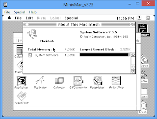
The About screen of System 9.0.4 under SheepShaver:


Microsoft Word 98, the last version to support System 9, with the well-known Office Assistant, running on SheepShaver:


Classilla is the only actively maintained web browser that still supports System 9 till this day. It sends a mobile user agent by default so that most web servers will return less heavy content suitable for low-end devices. In my experience, it is quite fast and displays many modern web pages nicely, including Wikipedia:


The equivalent web browser on a PC would be Dillo or D+ Web Browser. I use them on my Windows 98 machine with just 32MB of RAM to browse the modern web and they work quite smoothly.

This is a screenshot of MacWeb browser when running on System 9 showing Google search page. How much junk have we added to the Internet? HTML5, CSS, JavaScript, Flash and whatnot. All that needs to be shown for a Google home page is just a text box and two buttons:


I also tried the Mail application (which is actually Outlook Express) that comes with System 9. Unfortunately, it does not work with modern mail services such as Hotmail, Yahoo Mail or GMail. Although the software seems to support SSL and SMTP authentication, attempt to configure and log on to the mail server would simply crash SheepShaver, hang at "Connecting" forever, or report authentication errors. I guess the problem is related to SSL authentication, but without the time to verify and confirm this, the only way to get the Mail application to work is to find a provider that doesn't require SSL (which is very hard nowadays) or to use a local mail server such as hmail and configure the server to accept unencrypted connections.

The last screenshot in this article puzzles me. I use MacWeb from System 9 to browse Wikipedia and always receive an error page indicating "Unconfigured Domain". The error is persistent and Wikipedia website is still accessible from other browsers, including other System 9 browsers. Why is this the case since browsers only request for HTML content from the server and render them? While older browsers may fail to display modern contents, I would never expect them to display a domain error message for a totally functional site. This question is left as an exercise for the readers.


Creating calls and conferences using 3CX Call Control API

$
0
0
By default, 3CX provides the HTTP API to allow users to make calls on the PBX programmatically as well as changing some other extension settings. However, the HTTP API is pretty limited and a better way is to use the Call Control API to have more controls on how calls are created.

Although the Call Control API is available on both 3CX version 12 and 11, the library DLLs (3cxpscomcpp2.dll and sl.dll) used by the DLL are not interchangeable between the two versions. This means you will probably need to build two versions of your application referencing the different versions of the libraries if you wish to target both 3CX version 11 and 12. Also it is advised to keep a local copy of 3cxpscomcpp2.dll (and sl.dll) in your application and add a reference to the local copy, and not the version of the DLL found in the .NET Global Assembly Cache (GAC). In my test, referencing the GAC version may result in problems finding the 3CX assembly when the application is run on a different machine.

Making calls

To make a call connecting two extensions on the PBX, use the following method:

publicvoid MakeCall(
string dn_from,
string number_to
)

The source number, dn_from can be any internal number on the PBX and number_to can be any internal or external number. 3CX will call dn_from waiting for the call to be answered, upon which number_to will be called. When number_to picks up the call, dn_from and number_to will be able to talk to each other. This process is also known as callback.

While number_to can be any internal or external number, dn_from can only be an internal number. This means you will not be able to use this method to connect two arbitrary PSTN numbers via 3CX.

Conferencing on 3CX version 11

To initiate the simplest conference you can use

MakeCall(701, 101)

where 701 is the first conference extension on the system and 101 is the extension number. If 701 does not currently have any conference in progress, this will make a call to 101 informing the extension that a new conference will be created with the extension being the first participant and other people calling 701 will be able to join this conference. If a conference is already in progress, extension 101 will be able to join the existing conference.

The number of maximum simultaneous conference can be configured inside Settings > Advanced:


The above settings will create 4 conference extensions 701-704 on the system, viewable from System Extension Status from the 3CX web portal. A default conference extension 700 will also be created but cannot be used to make conference calls programmatically. From the call control API, extension 700 will be treated as a ConferencePlaceExtension with IsGateway property set to TRUE. User can still call 700 to create a new conference.

To have more controls on the created conference, use the following method:

publicvoid MakeCall(
string dnNumber,
Dictionary<string, string> parameters
)

where dnNumber is a conference extension which is not a gateway and parameters is dictionary containing the following parameters:

"tojoin" - number to dial. Specifies destination of call.
"PIN" - the pin of this conference. Can be empty.
"noname" - "0" or "1". Only for initial call. Conference place will not ask new members to pronounce name before entering this conference call but will ask to confirm participation. Will inform participants about joining and leaving but without name.
"instant" - "0" or "1". Only for initial call. Conference is instant. Conference place will not ask member to confirm participation

For example, to create a conference to extension 100 that begins immediately, does not ask members for name or PIN code, use the following set of parameters:

{"tojoin":"100", "PIN":"", "noname":"1", "instant":"1"}

Conferencing on 3CX version 12

On 3CX version 12, major changes havebeen implemented in the conference architecture and associated APIs. There are no longer separated conference extensions (e.g. 701-704) on the system. Rather, there is only a single conference extension (700) and each extension will have its own conference slot which can hold conference calls for that extension. The number of simultaneous conferences is also removed from 3CX settings:


To create a simple conference, you can use

MakeCall(700**101, 101)

to use the dedicated conference slot on extension 101 to initiate a new conference that has 101 as the first participant.

Unfortunately, according to 3CX support, the method

publicvoid MakeCall(
string dnNumber,
Dictionary<string, string> parameters
)

is no longer supported as at 3CX version 12, despite still being mentioned inside the API documentation.

The ScheduleTheConference.cs sample provided with the API provides another method to create a new conference:

PhoneSystem ps =PhoneSystem.Root;
var stat =ps.CreateStatistics("S_SCHEDULEDCONF", args[1]);
stat.clearall();
stat["name"] = args[4];
stat["idstat"] = args[1];
stat["pin"] = args[3];
stat["startat"] =dt.ToUniversalTime().ToString(@"yyyy-MM-dd HH\:mm\:ss");
stat["target"] =args.Length>5? args[5] :"";
stat["numbertocall"] ="";
stat["email"] ="";
stat["description"] ="";
stat["emailtext"] ="";
stat.update();


However, despite much effort, I could not get this method to work on my 3CX setup. No errors are returned and no related events are found inside the 3CX system activity log. Even if I could get it to work, it will not create a new conference effectively since the method intention is to schedule a new conference to run in the future, not to start it immediately and monitor its progress. This means there is currently no way to have full control over the created conference on 3CX version 12.

Surprisingly, the new version of 3CX Phone for Windows is able to support creating, scheduling and maintaining conference:


My guess is that it uses a proprietary communication protocol to communicate with the 3CX server directly. Knowing that the phone application is built as a .NET Silverlight application, I tried to use Reflector to decompile it and although the source code is not obfuscated, the decompiled code still looks far too complicated. At this point it is not worth the time and efforts for me to attempt to identify the conference mechanism this way. 

See also:
Using 3CX Call Control API in a .NET application

Interfacing TEA5767 FM Receiver with PIC using I2C

$
0
0
I got myself a few pieces of cheap TEA5767 FM receiver modules from eBay and decided to try them out. The modules arrived safe and sound and looked very tiny. Notice the bottom right of the board, close to the two pins of the 32.768 kHz crystal, where the TEA5767's GND pin is connected:

BUS MODE pin should be connected to GND whereas W/R and MPXO pin should be left unconnected. I make a simple breakout board out of a small piece of veroboard from my junk box to be able to plug it into a breadboard for development work.


It is only then that the fun began. The module is using I2C interface, which requires just 2 control lines, SDA for data and SCL for clock. Since most of the sample code I found on the Internet for this TEA5767 module is targeting the Arduino (the PIC seems to be dying among the world of hobbyists thanks to tremendous marketing efforts to promote the Arduino), I will need to adapt it my PIC24FJ64GA002 using my software I2C library. The simplest code to tune the TEA5767 to a particular FM station is as follows:

#defineTEA5767_W 0xC0
#defineTEA5767_R 0xC1

voidtea5767_setFrequency(double frequency)
{
unsigned char frequencyH=0;
unsigned char frequencyL=0;
unsigned int frequencyB;

frequencyB=4*(frequency*1000000+225000)/32768;
frequencyH=frequencyB>>8;
frequencyL=frequencyB&0XFF;

i2c_start();
i2c_write(TEA5767_W);
i2c_write(frequencyH);
i2c_write(frequencyL);
i2c_write(0xB0);
i2c_write(0x10);
i2c_write(0x00);

i2c_stop();

}

Here comes a word of caution for those converting I2C code from the Arduino to the PIC. The Arduino is using 7-bit I2C addresses, which is 0x60, as specified in the TEA5767 datasheet, with read/write address determined accordingly. However, the PIC24FJ64GA002 that I am using and most other PICs use 8-bit I2C addresses, which consist of the original 7-bit address and another bit to indicate read/write operation. Therefore, the correct I2C address for the TEA5767 on a PIC is 0xC1 for reading and 0xC0 for writing. I wasted three days debugging this issue.

With the above code the TEA5767 is able to tune into my favourite FM station. The output, although very low, sounds good and clear when fed into a suitable amplifier (such as PC audio system) or a crystal earpiece.

Next comes the challenge of reading data from the TEA5767 to check for signal strength and other relevant information. I used the following code:

voidtea5767_readData(unsigned char* byte1, unsigned char* byte2, unsigned char* byte3, unsigned char* byte4, unsigned char* byte5)
{
i2c_start();
i2c_write(TEA5767_R);
*byte1 = i2c_rx(1);
*byte2 = i2c_rx(1);
*byte3 = i2c_rx(1);
*byte4 = i2c_rx(1);
*byte5 = i2c_rx(0);
i2c_stop();
}


However, despite various debugging efforts, the above code simply returned 0xFF for all the bytes. I even checked on an oscilloscope and indeed the SDA line remained high during the read operation. My software I2C library has always been working well with other stuff, including a DS621 temperature sensor, DS1307 RTC and several EEPROMs.

It was so tempting at this stage to conclude that the TEA5767 module that I received was partially faulty. Who knows, perhaps that is the case for my module which was purchased from Chinese eBay sellers. However, I decided to make one last attempt at it by using the PIC24 hardware I2C modules, instead of bit-banging it via software.

Using the sample code from here I was quickly able to write codes to read and write a 24C64 EEPROM using the hardware I2C module. The completed I2C helper code can be downloaded here. Surprisingly, when using hardware I2C, the TEA5767 responds properly with the proper status bytes. The signal strength (in percentage) and other information of the currently active FM station can be derived from the data bytes using the following code:

tea5767_readData(&byte1, &byte2, &byte3, &byte4, &byte5);
stereo = (byte3&0x80);
freq = ((((byte1&0x3F)<<8)+byte2)*32768/4-225000)/100000;
signal_level = (byte4 >>4) *100/16;


If the hardware I2C code does not work with your PIC, first try to use the second I2C module instead of the first I2C module. Some PIC24 devices have a silicon bug rendering the first I2C module inoperative. Secondly, if the code is working intermittently, try to add a 82pF capacitor connecting the SDA line to ground for each I2C device on the bus. It was not working for me initially until I realized that it seemed to work with the oscilloscope probe pin connected, and figured that the capacitor is necessary. The reason is apparently due to the parasitic capacitance on a breadboard affecting the rise time/fall time of the I2C clock line, although I have not had time to verify this in details. Finally, don't forget the pullup resistors on both SDA and SCL lines of the I2C bus, which need to be at least 4.7k.

One final note is that the TEA5767 output is too low even to be fed into a common 8-ohm speaker configuration of the LM386 audio amplifier. This is why most online tutorials suggest using TDA7052 as the amplifier instead. In my case, as I am using the LM386, a stereo to mono converter and a single transistor pre-amplifier stage is necessary before I could hear the audio in the speaker:

 Stereo to mono converter

Single Transistor Pre-amp

I hope this will be useful for other hobbyists who are also trying TEA5767 on a PIC.


Accessing 3CX Call Data Record (CDR) PostgreSQL database

$
0
0
In my previous post I described a method to read the 3CX CDR information by parsing the CDR log files created by 3CX.  Although this approach may look straight forward from a programming point of view, as the number of call grows, problems will arise due to the reliance on the undocumented CDR file format and the needs to read and parse hundreds of CDR text files just to get the call statistics. As a result, I decided to attempt to read the database directly to see if better performance can be achieved and this article will share some of my findings.

Database configuration

As 3CX uses a PostgreSQL database to store its CDR information, you will need a tool such as pgAdmin to open the database. The database logon credentials can be found among the last few lines of the 3CXPhoneSystem.ini file located in the C:\Program Files\3CX PhoneSystem\Bin folder:

[CallReports]
USERNAME=logsreader
DATABASE=phonesystem
PORT=5480
DRIVER=PostgreSQL Unicode
ReadOnly=1
SERVER=localhost
PASSWORD=*******************


Add a new server in pgAdmin using the above credentials and you should be able to connect:


Database tables
 
The logsreader account only has access to some tables in the database, mostly tables with call history information and some other tables with information on the 3CX setup configuration, which perhaps can also be retrieved using the Call Control API.

The tables that contain the CDR are calldetails, callhistory2 and callhistory3. In my tests, table callhistory2 is always empty despite a large number of calls on the PBX. The remaining two tables, calldetails and callhistory3, store call information and are described below.

Table calldetails

This table contains information on each leg of the call, including the caller, destination number, timestamp and call status. Most useable columns should be self-explanatory from their names. Other important columns are described below:
  • idcalldetails: primary key of the table
  • idcallhistory2: the ID that identifies the same call in table callhistory2 and table callhistory3
  • is_tooutside: TRUE if the call targets an external number which is not an extension on the PBX (and has to be terminated via a configured gateway)
  • is_compl: whether the call was completed successfully, from the PBX point of view. For most calls (even for unanswered calls), this value will be TRUE. It will only be FALSE if an unexpected problem on the PBX occurred during the call.
  • status: the status of the call. Possible values are:        
Connecting = 0,
Answered = 1,
DestBusy = 2,
DestNoAnswer = 3,
DestNotAvailable = 4,
NotAnswered = 5,
Completed = 6,
DstUnknown = 7

Table callhistory3

This table stores overall information for each call. Important columns are described below:
  • idcallhistory3: primary key of the table
  • callid: the history ID of the call. This is the same ID that you will find in the 3CX CDR. It will look something like "00000BD4DFFBDF88_1".
  • is_answ: whether the call was answered by at least one party. If a call reaches a digital receptionist (IVR), is_answ is probably TRUE immediately after the calls reaches the PBX. If a call reaches a queue, is_answ will probably not be TRUE until it is diverted to a queue member. If an answered call is later forwarded to another party which does not answer the call, the is_answ flag remains TRUE.
  • is_fail: TRUE if the call could not be completed. For most calls, this flag should probably be FALSE unless an unexpected error occurred during the call.
  • is_compl: TRUE if at least one segment of the call is completed successfully.
  • is_fromoutside: TRUE if the call is from an external number which is not an extension on the PBX. For example, from a user who calls a DID number assigned to a configured gateway on the PBX. 
  • callerid: the number of the originating number of the call. If is_fromoutside is TRUE, this will be the external caller number. 
  • group_no: the number of the queue from which the call originates. If the call is not from a queue, this field is empty.
  • callchain: the semicolon separated list of all participants involved in the call 
  • rec_file: path to the WAV recording of the call, if recording is enabled.
Difference between callhistory3 and calldetails tables

While table callhistory3 stores overall information for each call, table calldetails stores information for each leg of the call. To illustrate the difference, if extension 10009 called the queue number on 80001 and was diverted to extension 10010 which is a member of the queue, you will see the following 2 records from table calldetails:


 And only 1 record from table callhistory3 showing overall information about the call:


The 2 records from table calldetails have idcallhistory2=19903 to indicate that they belong to the same call having a history ID of 00000BDA221D1253_4 in the callhistory3 table.

The status column is missing from table callhistory3, as different segments of the calls might have different statuses. However, from table callhistory3, you can still check whether the call was answered (is_answ and answertime column) and whether it was completed without errors (is_compl and is_fail columns).

Useful SQL queries

One of the objectives during my experiment is to write the SQL queries to extract the call reports in a format similar to the 3CX Web Report tool (available at http://localhost:5000/Reports). Suprisingly, with some understanding and experimenting with the database, this is a matter of tweaking some SQL queries to retrieve the information I need.

For example, to get the total calls made to the queue on the PBX reported by 3CX in Call Center Statistics Report > Detailed Queue Statistics - All Queues, we use the following query (assuming 80001 is our queue number):
SELECT*FROM calldetails WHERE  dest_dn ='80001'AND (status=5OR status=6)
Take note that the number of calls made through the queue returned from the above query (and reported by 3CX) may not be correct depending on how your queue is configured. For example, if I configure my queue to forward to another digital receptionist announcing "High Call Volume" after 30 seconds of waiting, and divert the caller back to the queue after the announcement, each "High Call Volume" announcement will add 1 entry to the database, resulting in an exaggerated number of reported calls to the queue.  To retrieve the true list of unique calls made through the queue on the PBX, we improve the query as below:

SELECT*FROM callhistory3 WHERE idcallhistory3 IN
(
SELECT DISTINCT idcallhistory2 FROM calldetails
INNER JOIN callhistory3 ON calldetails.idcallhistory2=callhistory3.idcallhistory3
WHERE calldetails.dest_dn ='80001'AND (calldetails.status=5OR calldetails.status=6)
)
The following query returns the number of calls to the queue that were answered by an operator:

SELECTCOUNT(DISTINCT idcallhistory2) FROM calldetails 
INNER JOIN callhistory3 ON calldetails.idcallhistory2=callhistory3.idcallhistory3
WHERE calldetails.dest_dn ='80001'AND (calldetails.status=5OR calldetails.status=6) AND (callhistory3.answertime IS NOT NULL)

Total number of abandoned calls, e.g. called to the queue that were never answered by an operator:

SELECTCOUNT(DISTINCT idcallhistory2) FROM calldetails 
INNER JOIN callhistory3 ON calldetails.idcallhistory2=callhistory3.idcallhistory3
WHERE calldetails.dest_dn ='80001'AND (calldetails.status=5OR calldetails.status=6) AND (callhistory3.answertime IS NULL)

Total taktime for answered calls made through the queue:

SELECTsum(endtime - answertime) FROM
(
SELECT DISTINCT idcallhistory2, callhistory3.answertime, callhistory3.starttime FROM calldetails
INNER JOIN callhistory3 ON calldetails.idcallhistory2=callhistory3.idcallhistory3
WHERE calldetails.dest_dn ='80001'AND (calldetails.status=5OR calldetails.status=6) AND (callhistory3.answertime IS NOT NULL)
)
AS result 
The returned value does not match the 'Total Queue Talk Time' parameter in the 3CX report as it counts the call duration from the moment the queued call is answered until the call is terminated, which may include time spent on other legs of the call if the queued call is diverted to other parties. On the other hand, the 3CX report only calculates the duration of the segment of the call which involves the queue number and does not include the time spending on other call segments.

To retrieve all calls that have been made on the PBX excluding calls made to the queue, use the following query (assuming 80001 is the queue number):

SELECT*FROM callhistory3 WHERE from_no <>'80001'

The result will be almost identical to the list of calls found in the Call Statistics Report > Call Logs section of the 3CX web report tool.

You will notice that the field status is missing from the returned value, as it is not available in the callhistory3 table. To get the detailed status of the call (e.g. answered, busy, no answer, invalid number, etc.), use the following query:

SELECT
DISTINCT ON(idcallhistory3)
callid, from_no, callerid, to_no, is_answ, callchain, status, calldetails.is_compl,
is_fail, is_fromoutside, group_no, recfile FROM callhistory3
INNER JOIN calldetails ON calldetails.idcallhistory2 = callhistory3.idcallhistory3
What the query does is to join the returned result with table calldetails to get back the field status. Because a call may have multiple legs, with each leg having different status, we need to use the special DISTINCT ON keyword of PostgreSQL to only retrieve the status of the first leg of the call in the final result. If the call has multiple legs with different status, this field may not be reflective of the overall status of the call, in which case the is_compl, is_answ and is_fail fields will need to be examined.

Accessing the database from .NET

.NET does not have built-in support for PostgreSQL databases and the use of an ODBC driver is needed to access the 3CX database from a .NET application. You will then need to add a DSN under Control Panel > Administrative Tools > ODBC Data Sources that points to the 3CX database:


Queries can now be executed using the OdbcDataConnection class:

OdbcConnection connection =newOdbcConnection("DSN=3CXDB");
connection.Open();
string query =String.Format("SELECT COUNT(idcalldetail) FROM calldetails");
OdbcCommand command =newOdbcCommand(query, connection);
OdbcDataReader reader =command.ExecuteReader();
reader.Read();
int count =reader.GetInt32(0);
reader.Close();
connection.Close();

If your program is to be run as a Windows Service, it is best to add the DSN under System DSN (which the Local System account has access to), and not User DSN, otherwise accessing the DSN may fail with error "Data source name not found and no default driver specified" unless the service is configured to run as system administrator. Also it is advised to install the version of the ODBC driver that matches the architecture of your application. For example, if the application is 64-bit, the 64-bit PostgreSQL ODBC driver should be installed. In my case, my application is also using the 3CX Call Control API which uses the 64-bit libraries that come with the 3CX installation on a 64-bit Windows machine, and both the application and the ODBC driver have to be 64-bit versions.

See also:

3CX Call Data Record (CDR) output file format
Using 3CX Call Control API in a .NET application 
Integration of 3CX Phone System with Tariscope  - athird party reporting tool for 3CX. 

Interfacing VS1053 audio encoder/decoder module with PIC using SPI

$
0
0
To fulfill my wish of building an MP3 player on top of a 16-bit PIC (PIC24FJ64GA002), I purchased a VS1053 audio encoder/decoder module from eBay. The VS1053, manufactured by VLSI, is capable of decoding WAV/MP3/WMA/OGG/AAC/MIDI files, as well as FLAC format with the help of a software plugin. It is also capable of recording audio, either via the Line In input, or via a microphone, which comes installed in the breakout board that I purchased.

Module pinout

The front and back of the module, with the 5x2 connection header: 


To be able to use it on a breadboard for prototype development, I made a small breakout board for the connection header using a small piece of stripboard. The pinout description for the connection header is below:

MOSI - Master Out Slave In
MISO - Master In Slave Out
SCK - SPI Clock Signal 
XCS  - Send Command (Active Low)  
XDCS - Send Data (Active Low)
XRST - Reset (Active Low)
DREQ - Data Request

The module uses Serial Peripheral Interface (SPI) to communicate with the microcontroller. I used the code from here and adapted it to work with my PIC24FJ64GA002 hardware SPI modules.  The completed modified code can be downloaded here.

Audio playback

The VS1053 has a few registers which control its operations. Among them, the more important registers are:

SCI_MODE   - Controls the operation of the module
SCI_STATUS - Controls information on the current status of the module
SCI_BASS - Controls the bass boosting DSP algorithm used for playback
SCI_CLOCKF - Controls the chip clock frequency
SCI_VOL - Controls playback volume 
 
To use the VS1053 module to play and record audio files, I converted the Adafruit's Arduino library for the VS1053 to compile under Microchip C30 compiler. To initialize the module, set the microcontroller SPI speed to 1MHz, pull down pin XRST for a short while to perform a reset and then read the value of register SCI_MODE, which should contain the default value of 0x4800:

// primary scaler 4:1, secondary scaler 4:1 @ 1MHz 
spi2Init(0b00010010);

//Deselect Control
MP3_XCS = 1;

//Deselect Data
MP3_XDCS = 1;

// hardware reset
MP3_RESET = 0;
delay_ms(10);
MP3_RESET = 1;
delay_ms(10);

//Set initial volume (20 = -10dB)
vs1053_SetVolume(volDefault, volDefault);

//Read the SCI_MODE register
vs1053_ReadRegister(SCI_MODE);

When ready for audio playback, write to SCI_CLOCKF register to set the multiplier and increase the clock speed of the VS1053, followed by increasing the PIC SPI clock speed:

//increase the VS1053 internal clock multiplier and up our SPI 
vs1053_WriteRegister(SCI_CLOCKF, 0x60, 0x00); //Set multiplier to 3.0x

// Internal clock multiplier is now 3x.
// Therefore, max SPI speed is 5MHz. 4MHz will be safe.
// primary scaler 1:1, secondary scaler 4:1.
SPI2CON1 = SPI2CON1 | 0b00010011;

The above code assumes that the PIC is running at 32MHz. When the setup is completed, supported files can be playing by simply sending data to the module via SPI:

void vs1053_play(unsigned char* data, unsigned int len)
{

unsigned char*p;
int i;

p =&data[0]; // Point "p" to the beginning of array
while(p <=&data[len -1]) {
while(!MP3_DREQ_IN) {
//DREQ is low while the receive buffer is full
//You can do something else here, the bus is free...
//Maybe set the volume or whatever...
}

//Once DREQ is released (high) we can now send 32 bytes of data
MP3_XDCS =0; //Select Data
spi2Write(*p++); // Send SPI byte
MP3_XDCS =1; //Deselect Data
}

while(!MP3_DREQ_IN) ; //Wait for DREQ to go high indicating transfer is complete
MP3_XDCS =1; //Deselect Data
}


Except for a few problems with SPI setup on my PIC24, my completed code works upon first try. The played music sounds very clear and the output current is strong enough to be able to be listened through a headphone. Using Microchip MDD library, I was able to interface the PIC with my 128MB SD card and play WAV/MP3/WMA/OGG/AAC files from the card smoothly. For MIDI files, only midi type 0 (single track) files are supported by the VS1053. If your MIDI files are of type 1 (multi-track), you'll need to convert them to type 0 before they can be played. You can download many sample MIDI type 0 and type 1 files for testing here.

According to the datasheet, FLAC files are supported by loading a software plugin. I have not tried this, however.

Unexpected problem: floating XTEST pin!

In the midst of the experiment I suddenly realized that my VS1053 module stopped working. It could no longer play any audio file and SCI_MODE always read 65424 (0xFF90) upon power on, instead of the default 0x4800. When this happened, other SPI read/write operations still appeared to be working fine, e.g. written values could still be read back properly. Attempting to write the default value of 0x4800 to SCI_MODE was successful, but the module still could not play any audio data.

I decided to put the board away for a while, remove the power and try again. Surprisingly, everything worked again upon the first try, but only exactly once! Upon the second run the module exhibited the same beaviour (0xFF90 for SCI_MODE at startup) again. I tried again with a fresh VS1053 module and again, it could only work once.

What was exactly the problem? The module could not have been totally broken because SPI read/write was still working fine. And it was also unlikely that two different modules were damaged in exactly the same manner. At this point I suspected that since some parts of the code were incorrect, it could have altered the contents of non-volatile memory of the VS1053 and causing permanent damage. Searching the Internet revealed that other people have similar inconsistent behaviors and suspected non-volatile memory corruption of the VS1053. However, posts on the VSDSP forum confirmed that the VS1053 does not have non-volatile memory, so the problem must have been something electrical.

The real problem, after much research effort, is the XTEST pin on the VS1053. This pin must be connected to VDD for things to work consistently. Many clone boards, including earlier versions of the Sparkfun VS1053 boards and those sold on eBay, leave the XTEST pin unconnected, leading to unspecified behavior. I referred to the datasheet for the location of XTEST, which is pin 32 in the LQFP-48 package:


After several checks I confirmed that pin XTEST was indeed floating. Take note that since the PCB may be multi-layered, you can't judge whether a pin is floating just because it looks unconnected as it may be connected via the hidden layers of the PCB. Although the pins are tiny and appear very difficult to solder using a generic soldering iron, I was lucky as all I needed to do was to connect XTEST to VDD, which happens to be the neighboring pin 31 (CVDD3). A single drop of solder between the two pins is all that is needed and the modified board is below (the soldered pins are in red):


With this modification, the board works well and there are no longer any intermittent problems. If you still have problems, make sure that GPIO0 and GPIO1 pins are also connected to GND. Some boards have GPIO0 connected to GND while GPIO1 connected to VDD and the module will boot up in real-time MIDI mode instead.

Audio recording

The module supports recording, either via the on-board microphone or via the Line In input. Natively, Pulse Code Modulation (PCM) encoding is supported, in either linear (uncompressed) or ADPCM (compressed). Encoding into OGG format is supported via software plugin. PCM are encoded in 16-bit little endian format.

To enter recording mode,  set the bit SM_ADPCM and SM_RESET of the SCI_MODE register. Bit SM_LINE1 may be set if recording via Line In, otherwise clear it to record via the microphone. Page 53 of the datasheet explains this in details. Take note that if you're recording via the microphone, set SCI_AICTRL3 bit 0-1 into left channel mode, otherwise the default is stereo (both channels) and the output audio will be distorted since the microphone provides single channel (mono) only.

I tried to perform a linear PCM recording and write the data to an SD card. At 8kHz and 16-bit, the output file consumes approximately 16KB per second. I performed a benchmark of the FSfwrite function of the MDD library by opening a file and appending 0xFF to it. The speed is approximately 18KB/s with the PIC running as 32MHz. The actual writing speed when recording will be lower as the PIC is also busy communicating with the VS1053 to retrieve the audio data. As a result, the recorded audio file appears to be choppy and it seems further optimization is needed for recording to work properly.

As this is a hobby project, I decided not to proceed with improving the recording performance. Using this module for audio playback should be good enough on a PIC24. The C30 code to play audio files using VS1053 can be downloaded here for those who are interested.

Experimenting with ST7920 128x64 graphical LCD on a PIC

$
0
0
This is a monochrome 128x64 graphical LCD using the ST7920 controller that I purchased from eBay:


The module is using a 20-pin standard 2.54mm connector, making it easy for prototype development on a breadboard:

According to the datasheet, the following communication modes are supported:
  • 8-bit mode. Data or instruction bytes are transferred via pin DB7-DB0.
  • 4-bit mode. Data or instruction bytes are separated into two parts. Higher 4 bits will be transferred through DB7-DB4, followed by the lower 4 bits. The DB3-DB0 pins will not be used and should be connected to ground. 
  • Serial mode. This is done by pulling down the PSB pin. When enabled, communication will only require 4 pins in total. Only writing data is supported in serial mode
Unfortunately, the board that I purchased has the PSB pin permanently connected to VCC. Hence, only parallel communication is possible. To cut down on the number of output pins required, I have selected 4-bit mode, instead of 8-bit.

The LCD supports both graphics and text modes:
  • Maximum 16 characters x 4 lines in text mode
  • 128x64 resolution in graphics mode.
The following code performs LCD initialization and configures 4-bit communication in text mode:

voidLCD_Init(void) 
{
LCD_REST=1;
LCD_REST=0;
delay_ms(5);
LCD_REST=1;

delay_ms(50);

LCD_WriteCommand(0b00100000);
delay_ms(5);

LCD_WriteCommand(0b00100000);
delay_ms(5);

LCD_WriteCommand(0b00001100);
delay_ms(5);

LCD_WriteCommand(0x01);
delay_ms(5);

LCD_WriteCommand(0x06);
delay_ms(5);

LCD_WriteCommand(0b00000010);
delay_ms(5);
}

After the LCD has been initialized, the following function will display a string on the LCD:

void LCD_TextDisplayString(unsigned char line, char* string)
{
unsigned char addr,i;
if(line==1)
addr=0x80; //The first line address
elseif(line==2)
addr=0x90; //The second line address
elseif(line==3)
addr=0x88; //The third line address
elseif(line==4)
addr=0x98; //The fourth line address

LCD_WriteCommand(addr);

for(i=0;i<16;i++)
LCD_WriteData(*string++);
This is how it will look when displaying 4 lines of text:
Despite the large screen resolution, the default text mode only allows me to display up to 64 characters on the screen due to the thick font. My next attempt is to use graphics mode, so that I can use my custom font and display more characters. The following code shows how to enable and disable the graphics mode on this LCD:
voidLCD_EnableGraphics(void)
{
LCD_WriteCommand(0x20);
delay_ms(1);
LCD_WriteCommand(0x24);
delay_ms(1);
LCD_WriteCommand(0x26);
delay_ms(1);
}

voidLCD_DisableGraphics(void)
{
LCD_WriteCommand(0x20);
delay_ms(1);
}

Similar to the Nokia 5110 LCD, every 8 pixels on this LCD will consume a single byte in the display memory space. With that knowledge I was quickly able to use my custom 5x7 bitmap font and display more characters. The following picture is the display showing information from various sensors that I have interfaced with the PIC24FJ64GA002. It can show up to 16x8=128 characters:
Various graphics that I manage to display on this LCD:
The full C30 source code for this LCD can be downloaded here. If you are interested, the syntax highlighting of the source code in this article is done using this tool.

Experimenting with ST7735 1.8" 128x160 color LCD on a PIC microcontroller

$
0
0
This tiny 1.8" LCD module is the second color LCD that I successfully attempted (the first is the Nokia 3510i LCD). The breakout board which I purchased from eBay also comes with an SD card socket:


The pinout for the board is as follows, inclusive of the SD card connections: 

1.  GND
2.  VCC 
3.  NC
4.  NC
5.  NC
6.  LCD RESET
7.  LCD A0 (R/S)
8.  LCD SDA
9.  LCD SCK
10. LCD CS
11. SD SCK
12. SD MISO
13. SD MOSI
14. SD CS
15. LED+
16. LED-

This LCD controller, ST7735, uses SPI for communication and requires just 5 data lines, namely RESET, A0, SDA, SCK and CS. Of particular note is the A0 line, also known as R/S, which indicates whether the bytes being transferred should be interpreted as command or as pixel data. Although SPI communication should preferably be done using the hardware SPI module (there are two on my PIC24FJ64GA002) for faster display speed, it can also be done via bit-banging if hardware SPI is not available. The following function will send a byte via SPI using software:

voidwrite_spi_byte(unsigned char c){
char x;
for(x=0;x<8;x++){
LCD_SCK = 0;
LCD_SDA = 0;
if(c & 0x80)
LCD_SDA = 1;
LCD_SCK = 1;
c <<= 1;
}
}

I converted the Adafruit's Arduino library for this LCD to compile under Microchip C30 compiler for my PIC24FJ64GA002 and the LCD is able to draw some graphics nicely: 

Using the bundled SD card socket and Microchip MDD library, together with my custom 5x7 font, I was able to display some SD card information on the LCD: 


The board I purchased has an AMS1117 on-board regulator and expects at least 5V to be supplied to VCC to be able to generate 3.3V for the LCD and SD card to work. I did not know this and supplied 3.3V to VCC initially, only to find out that the SD card worked intermittently while the LCD still worked well. If you have problems with the SD card on this module, check if this is the case. 

The ST7735 controller supports up to 262,144 (218) colors. However, to be able to use 262K colors, for each pixel, 18-bit of data have to be transferred via SPI. Since this increases the complexity. I have decided to stay with 65,536 colors (16-bit) colors, where pixel data can be transferred nicely just by using 2 SPI writes.  

In 16-bit color mode, the LCD expects pixel data to be in RGB565 format. The following will convert from the well-known RGB888 (24-bit color) format to RGB565: 

#defineRGB565(r,g,b) ((((r>>3)<<11) | ((g>>2)<<5) | (b>>3)))   

An interesting point to note about this LCD is that there seems to be two variants with slightly different behaviors. If your module comes with a black tab, the BLUE and RED byte of each pixel will be swapped, resulting in the wrong color being displayed. If your module has a red or green tab, the byte order for each pixel will be correct.  

To fix this issue, you can change the above RGB565 macro to swap the red and blue byte, or you can change the value of the MADCTL register during initialization: 

writecommand(ST7735_MADCTL);

// R and B byte are swapped
// writedata(0xC8);

// normal R G B order
writedata(0xC0);

Various bitmaps from my SD card as shown on the LCD:


The C30 source code for this LCD can be downloaded here.

Showing an input box on Windows Phone 7

$
0
0
In a Windows Phone 7 application, how can you quickly show a dialog asking the user to enter an input string without creating a new XAML page? The easiest method would be to call Guide.BeginShowKeyboardInput from the Microsoft.Xna.Framework.GamerServices namespace, which offers a similar user experience to the .NET framework's InputBoxmethod, available in the .NET framework as part of the Microsoft.VisualBasicnamespace.

First you will need to add references to Microsoft.Xna.Framework and Microsoft.Xna.Framework.GamerServices to your project. After that, use the following code:

Guide.BeginShowKeyboardInput(Microsoft.Xna.Framework.PlayerIndex.One, "Title goes here", "Description goes here", "default text", newAsyncCallback(Value_Entered), null);

The prompt will be shown:


Handle the response by:

void Value_Entered(IAsyncResult res)
{
string value =Guide.EndShowKeyboardInput(res);
}

Notice that the returned value will be an empty string when the CANCEL button is clicked or when the user does not enter any value and simply clicks the OK button. Another restriction is that the dialog will automatically be closed if the application enters the background (e.g. when the Windows key is pressed) and will not be redisplayed when the application is subsequently activated. This makes the use of BeginShowKeyboardInput unsuitable for scenarios when the user needs to leave the application temporarily before the code can be entered, for example when the dialog asks for a verification code sent to the user's phone number as part of the mobile number verification process and the user needs to leave the application to open the Messaging application to check for new messages.

In those scenarios, a more suitable approach is to use the InputPrompt class available is the coding4fun controls toolkit for Windows Phone. To install this, from Visual Studio Project menu, select Manage NuGet Packages and install the Coding4fun Toolkit - Controls package:


After the installation, restart Visual Studio and you will be able to use the InputPrompt class. If you encounter the error "You are trying to install this package into a project that targets ... but the package does not contain any assembly references that are compatible with that framework.",please reinstall the latest version of NuGet using the Tools>Extensions and Updates menu in Visual Studio.

You can show the input message by using the following code:

InputPrompt input =newInputPrompt();
input.InputScope=newInputScope { Names = { new InputScopeName() { NameValue=InputScopeNameValue.Number} } };
input.Completed+= input_Completed;
input.Title="Basic Input";
input.Message="I'm a basic input prompt";
input.Value="";
input.MessageTextWrapping=TextWrapping.Wrap;
input.IsCancelVisible=true;
input.Show();

The dialog will be shown:


Handle the response by:

void input_Completed(object sender, PopUpEventArgs<string, PopUpResult> e)
{
string value =e.Result;
}

With this approach, the dialog will still remain open when the user leaves the application and comes back, which is better than using the BeginShowKeyboardInput method. Take note that this will only work if the user returns to the application by holding the BACK key and selecting the application icon. If the user clicks on the application icon in the Start menu, due to a restriction in the Windows Phone 7 SDK, the application will be restarted from the beginning and the input prompt will no longer be shown. On Windows Phone 8, the user can also return to the input prompt using the Start menu icon if the following modification is added to the task entry in the WMAppManifest.xml fileto enable fast app resume: 

<DefaultTaskName="_default"NavigationPage="MainPage.xaml"ActivationPolicy="Resume"/>

For more information on the customizations that can be done on the InputPrompt class, refer to this.
Viewing all 63 articles
Browse latest View live