Recently I started to regain some interest in embedded systems, and start to experiment with PIC micro-controllers. After some successful attempts with standard character LCDs using using the HD44780 controllers, I decided to get some Nokia LCD modules from eBay to explore.
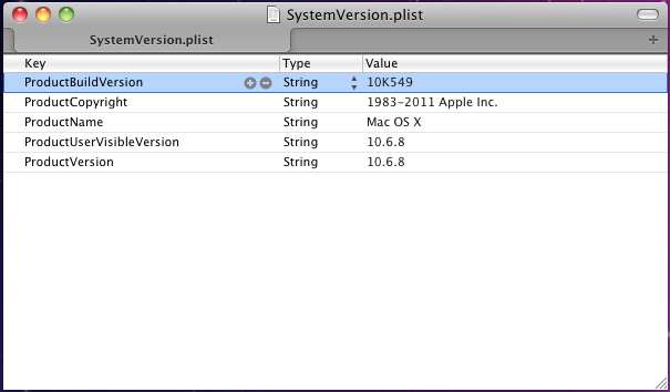
The 2 LCD modules I purchased are for the 3510i and 5110 models. Both have built-in controllers which use Serial Peripheral Interface (SPI). The following are the pinout for my modules, notice that pin assignments may vary slightly.
LCD pinout
Nokia 5110:
![]()
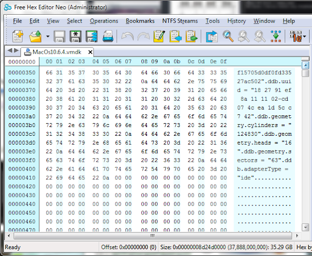
Nokia 3510i:
![]()
The only different here is pin #5 which is used as data/command selection for the 5110, and unused for the 3510i.
Voltage difference: 5.5v vs3V
Both LCDs are designed to work with 3.3V, but due to an internal voltage clamp 5V can be used for SCLK, SDATA, REST, D/C and CS as long as a current limiting resistor (around 10k) is connected in series for each line. 3.3V should still be applied to VCC and the LED supply. I have tried using voltage dividers, which did not work, perhaps due to the LCD varying internal resistance and current consumption.
With the above connections we can only write to the LCD but can't read back the LCD response because 3.3v is not high enough to register as logic '1' in the PIC. Luckily reading from the LCD is not required for basic operations; all that is needed is sufficient delay after each operation to make sure the LCD is ready for next command.
I have chosen the PIC16f88 simply because it's available in my junk box. However, as the 16f88 does not have dedicated hardware SPI required by the LCD modules, bit-banging has to be used to simulate SPI. Although this usually means complicated code and lower throughput, it does not matter as all I wanted is to get the LCD to display something useful ;)
LCD Memory Map
The 5110 LCD is monochrome, uses the PCD8544 controller and has a resolution of 48 rows × 84 columns. Each 8 pixels on a single column consumes a single byte on the LCD memory map. It takes 504 bytes to fill the entire LCD.
The 3510i LCD has 97x66 resolution and can operate in either 256 or 4096 colors. Since there seems to be little difference between 256 and 4096 colors due to the small resolution, I have chosen 256 colors for simplicity. Each pixel on the LCD is represented by a single byte and filling the entire LCD takes 6402 bytes in 256-color (8-bit) mode.
Sample code: displaying test patterns
The following code shows how to display all black pixels on the Nokia 5110 LCD. Notice that LCD initialization code is not shown.
The following code shows how to display a selected color on the 3510i LCD:
Displaying text and graphics
Up until now you can only display test patterns on the LCDs. The use of a bitmap font (and extra code) is required if you want to display any useful text. I have chosen a 8x12 font for the 3510i LCD, and a 5x8 font for the 5110 LCD. The font, together with any graphics to be displayed, will be stored in a 24C64 (8Kbytes) I2C EEPROM. To program the EEPROM, I use the I2C version of the PonnyProg programmer. Notice that this may not work on newer PCs where the available current from the serial port is limited and will never work with a USB-to-serial converter. In my experiment, I made a stupid mistake of adding a LED via a 470 ohm resistor to show activity during programming. This result in data corruption and verification errors after programming due to excessive current consumption. Changing the resistor to 2k worked fine, although the LED is much dimmer.
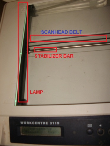
With the EEPROM to store font and graphics, the 5110 LCD could now display text and some monochrome bitmap:
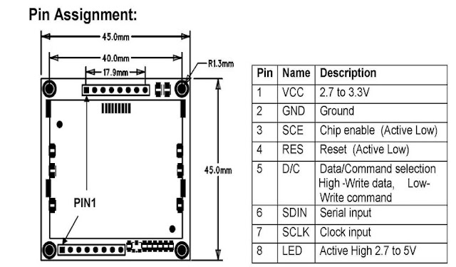
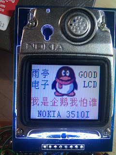
The 3510i LCD could do a much better job ;)
![]()
![]()
Notice that the serial port connector is for debugging purposes only.
The entire source code is attached here. The contents of the EEPROM is included with the source code and named eeprom.bin.![]()
The 2 LCD modules I purchased are for the 3510i and 5110 models. Both have built-in controllers which use Serial Peripheral Interface (SPI). The following are the pinout for my modules, notice that pin assignments may vary slightly.
LCD pinout
Nokia 5110:
Nokia 3510i:

The only different here is pin #5 which is used as data/command selection for the 5110, and unused for the 3510i.
Voltage difference: 5.5v vs3V
Both LCDs are designed to work with 3.3V, but due to an internal voltage clamp 5V can be used for SCLK, SDATA, REST, D/C and CS as long as a current limiting resistor (around 10k) is connected in series for each line. 3.3V should still be applied to VCC and the LED supply. I have tried using voltage dividers, which did not work, perhaps due to the LCD varying internal resistance and current consumption.
With the above connections we can only write to the LCD but can't read back the LCD response because 3.3v is not high enough to register as logic '1' in the PIC. Luckily reading from the LCD is not required for basic operations; all that is needed is sufficient delay after each operation to make sure the LCD is ready for next command.
I have chosen the PIC16f88 simply because it's available in my junk box. However, as the 16f88 does not have dedicated hardware SPI required by the LCD modules, bit-banging has to be used to simulate SPI. Although this usually means complicated code and lower throughput, it does not matter as all I wanted is to get the LCD to display something useful ;)
LCD Memory Map
The 5110 LCD is monochrome, uses the PCD8544 controller and has a resolution of 48 rows × 84 columns. Each 8 pixels on a single column consumes a single byte on the LCD memory map. It takes 504 bytes to fill the entire LCD.
The 3510i LCD has 97x66 resolution and can operate in either 256 or 4096 colors. Since there seems to be little difference between 256 and 4096 colors due to the small resolution, I have chosen 256 colors for simplicity. Each pixel on the LCD is represented by a single byte and filling the entire LCD takes 6402 bytes in 256-color (8-bit) mode.
Sample code: displaying test patterns
The following code shows how to display all black pixels on the Nokia 5110 LCD. Notice that LCD initialization code is not shown.
void lcd_5110_clear()
{
for(int i=0; i<84;i++)
{
unsignedchar row;
for(row=0;row<6;row++)
{
//all black pixels
char data =0xFF;

            lcd_5110_send(0x40+ row,0);//Y address
            lcd_5110_send(0x80+ i,0);//X address

//write to display memory
            lcd_5110_send(data,1);
}
}
}
The following code shows how to display a selected color on the 3510i LCD:
void addset(unsignedchar x1,unsignedchar y1,unsignedchar x2,unsignedchar y2)
{
send(0x2a,0);//column address set
send(x1, 1);
send(x2, 1);
send(0x2B, 0);//page address set
send(y1, 1);
send(y2, 1);
send(0x2C,0 );//memory write
}void LCD_Clear(unsignedint value,unsignedchar Color)
{
unsignedchar x, y;
addset(0,0,97,66);
for(y =0; y <67; y ++)
{
for(x =0; x <98; x ++)
{
send(Color, 1);
}
}
}
Displaying text and graphics
Up until now you can only display test patterns on the LCDs. The use of a bitmap font (and extra code) is required if you want to display any useful text. I have chosen a 8x12 font for the 3510i LCD, and a 5x8 font for the 5110 LCD. The font, together with any graphics to be displayed, will be stored in a 24C64 (8Kbytes) I2C EEPROM. To program the EEPROM, I use the I2C version of the PonnyProg programmer. Notice that this may not work on newer PCs where the available current from the serial port is limited and will never work with a USB-to-serial converter. In my experiment, I made a stupid mistake of adding a LED via a 470 ohm resistor to show activity during programming. This result in data corruption and verification errors after programming due to excessive current consumption. Changing the resistor to 2k worked fine, although the LED is much dimmer.
With the EEPROM to store font and graphics, the 5110 LCD could now display text and some monochrome bitmap:


Notice that the serial port connector is for debugging purposes only.
The entire source code is attached here. The contents of the EEPROM is included with the source code and named eeprom.bin.